

Phil Durbin
DeepSea Challenger is a solo manned submarine that conveyed National Geographic explorer in residence and film director James Cameron (famous for Avatar, Titanic, Terminator) to the deepest place on earth, 11km down in the Marianas Trench in March 2012.
Designed and built in Australia, the innovative submarine was based on a unique concept, the brain-child of underwater fanatics and submariners James Cameron and Ron Allum, and supported by Finite Elements (Australia)'s founding director, Phil Durbin who provided professional engineering advice, guidance and simulation driven engineering design.
This was a bold and ambitious project with a crushing timeframe for development that made extensive use of FEA and CFD simulation driven engineering design, without which it would simply never have succeeded in the timeframe.
Phil Durbin's engineering team at Finite Elements (Australia) Pty Ltd, a Tasmanian based technology and engineering company, provided the Sydney based project team, over a 6 year period, with the engineering design and analysis of the pilot capsule, the modular structural concept and detail design of the submarine body, co-development and manufacturing development of the patented IsoFloat buoyancy foam used as the primary material of construction, development of the submarine's composite material skin, and in-water flight performance predictions. Finite elements also designed unique high pressure test chambers (one of which is the largest in the Southern Hemisphere) for use in the manufacture and testing of the craft components. They delivered design support for many of the team's specially developed items such as lights, fastenings, camera housings, battery carriers, and more.
The Finite Elements' team used CFD extensively. Once the pilot sphere had been designed and tested to full ocean depth in a test chamber at Penn State University and following the development of the foam buoyancy material to the point at which it could be classed as an engineering material the project "go" button was pressed in earnest and the race began. In just 12 short months, the rest of the sub was designed and manufactured, achieving its full ocean depth dive a further 3 months hence.
The consequence? Everything had to work first up. Extensive simulation using both FEA and CFD meant that 1st up prototypes of many of the subs critical features just simply worked as required. Phil conceived a modular design concept and construction methodology which allowed rapid parallel development of the sub components; a methodology where an inventive simulation supported design development approach was essential.
Below we have described some of the CFD modelling undertaken:
 Thrusters
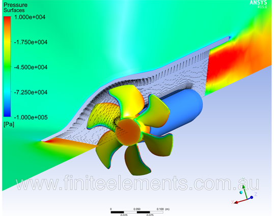
Propulsion for the sub is required when traversing the bottom, adjusting the distance from the bottom and slowing the sub's vertical ascent just before touchdown. Commercially available propellers from motor yacht bow thrusters were chosen because their thrust characteristics and ducted design could be rapidly adapted, saving critical development time. The electric motor units were specially developed to suit requirements of operation at full ocean depth. However, the performance of the propellers in delivering known thrust at various rpm was unavailable. We used CFD to model the propellers, in the ducted configuration complete with the motor housing, to predict their ability to drive the sub and to provide the torque speed curve necessary for design of the electric motor and motor controller.
Battery Housings
Water flow requirements, water duct sizing and water flow distribution orifices for the battery carriers (machined from Isofloat syntactic foam) were determined using a quick CFD analysis to ensure the battery case would be properly enveloped in seawater. The design resulted in a multiple single hose configuration where each hose delivered the necessary seawater to a group of four batteries. With enormous time pressure the manufacture of the battery carrier system proceeded on the basis that the CFD prediction was "close enough".
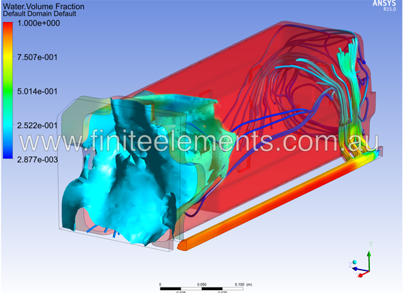
Battery box water flow quarter symmetric model. Surface of water (in blue) flooding out of carrier void around the battery cell.
LED lights
The light bank at the front of the sub was specially developed by Ron Allum (sub-conceptual co-designer and submariner) using his unique pressure balanced electronics system, where the electrical components are flooded with a silicone fluid in a housing pressurised to full ocean depth pressure, by virtue of a flexible diaphragm which forms part of the housing.
The lights are designed to operate submerged in seawater where heat is effectively conducted away to the seawater. However, it was possible that, if the lights were left on when not submerged in water, there would be an overheating risk that could cause unpredictable LED failure. To ensure that heat could be adequately conducted away from the entire LED array we used CFD analysis to study the transfer of heat generated by the LED's and circuit board through the housing body by both conduction and natural convection through the silicone fluid.
LED's toward the center of the array were shown to heat up to a level where their operation could prove unreliable. The LED's did prove marginal and were replaced with better quality units to ameliorate this issue.

LED light Silicone fluid flow patterns and light temperatures.
Ascent instability
The following video shows an earlier version of the sub ascending. It is a rather wild ride. 5th scale model testing validated the CFD results. Our team changed the shape of the top section of the submarine to be more rounded and this solved much of the issue, eliminating the rolling and yawing motions. The addition of the two fins seen in the final design (designed by the Deep Sea Challengers American team member and America's cup guru Bruce Sutphen) fine tuned the rotational stability around the Z axis (the vertical axis).
The simulation used CFX's dynamics capability. A six degree of freedom model was used with the sub modelled at the centre of a spherical moving domain. The sub surfaces were assigned all the correct inertial characteristics. This spherical domain was centred in a very large "ocean domain" with a deformable mesh and mesh motion interface to the sub domain. In this way, the sub could ascend 500 metres without the need for complex remeshing of either domain. Rotations and translations were allowed on the inner domain and translations at the outer domain to the inner domain interface.
DeepSea Challenger in-flight ascent model for an early version of the submarine design, created by Finite Elements Australia from Michele Durbin on Vimeo.
Sub horizontal travel
The sub was designed to have the lowest drag coefficient possible within the geometric constraints imposed by mass distribution and buoyancy distribution. The geometric constraints were significant, to get them out of balance meant that the centre of buoyancy compared to the centre of mass would cause the sub to lean forwards or backwards in the water column. Such issues would have further unwanted effects on inflight travel under thruster power, causing unwanted downward or upward flight. Even more complex was to position the centre of mass, centre of buoyancy and centreline of thrust such that applying the thrusters would not unnecessarily affect the trim of the sub when speeding up or slowing down. The centre of drag was set at the centreline of the thrusters so that the trim would not be affected during constant velocity flight.
The sub cross section was made in a tear drop shape to accommodate the outer dimensions of the pilot capsule and keep the size of the sub to an absolute minimum. The tail was extended just sufficiently to keep the water flow around the profile reasonably well attached. This necessitated the back of the profile to be hollow so as not to affect the buoyancy distribution.
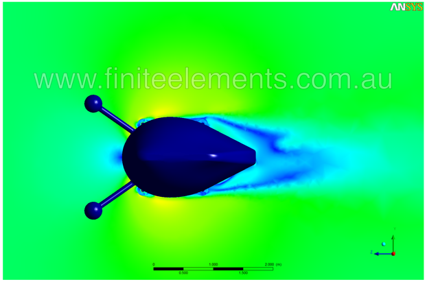
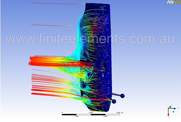
The aft of the sub profile is flat. It was found that a pointed profile led to an alternating trailing vortex and an uneven pressure distribution which would make the sub difficult to drive in a straight line. Even with the cut off "Kamm" tail, the sub still has some tendency to an uneven and transient velocity/pressure distribution as seen in the horizontal cross section below. The cross section shape of the sub was a compromise of many factors, the most problematical of which was the volume and buoyancy distribution. It was serendipitous that the flat "Kamm" tail made an ideal foot for the sub to sit on in its transport cradle, rather than the sharp trailing edge that was originally envisaged.
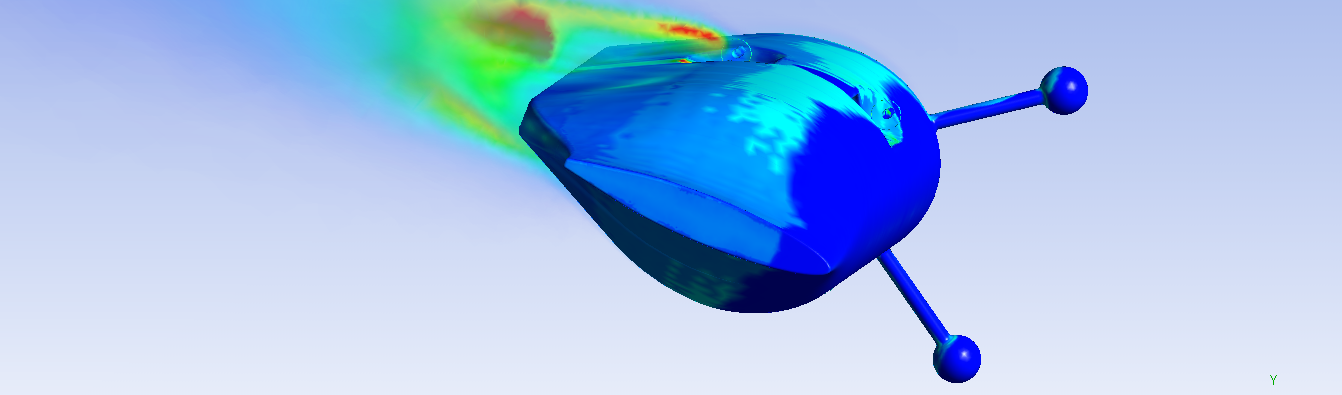
An interesting effect of the water jet that emanates from the thrusters was to create a low pressure region that pulled the streamlines at the trailing edge of the profile closely around the sub, creating better flow attachment across the aft sections of the profile, benefiting drag. This image of an early sub design iteration shows how the streamlines are sucked down toward the water jetting from the thrusters in forward flight (seen in light blue). This favourably assists the boundary layer to remain attached to the sub as it moves forwards.
Risk?
Many would call this project a seriously risky undertaking. As engineers, we are constantly pressured about risk, safety or commercial disaster.
When your client is on record as stating "safety is not the most important thing. I know this sounds like heresy, but it is a truth that must be embraced in order to do exploration. The most important thing is to actually go." then you, the engineer, start to worry if you will sleep at night if all goes wrong .... nobody wants a dead Cameron on their resume.
What does this philosophy mean for the engineer tasked with the design of the major structural components of a craft capable of withstanding full ocean depth pressure (114 MPa), required to be of manageable weight and size and built to an ambitious time schedule? How does the engineer balance the desirability of absolute certainty with the reality of “sufficient information” when time is of the essence?
The answer lies in an inventive ethos supported by virtual engineering simulation technology; the ultimate exploration vehicle for the inventive mind with a challenging destination.
The skill is in knowing when an exact answer is necessary and when a pragmatic approximation is good enough. Simulation was both a compass for design direction, and a risk management tool when exact answers were necessary for survival.
For more information on Phil and team at Finite Elements Pty Ltd, please visit their website.


