For this post, we'll discuss a topic which allows you to complement your understanding of global and local mesh controls that we have covered previously. Sweep meshing is a meshing method available in ANSYS Meshing that is important for all CFD users to understand and can be readily used to maintain high solver accuracy at the same time as reducing mesh cell counts (leading to a serious speedup in solve times).
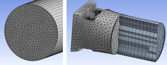
The Sweep Method begins by meshing a particular 'source' surface using either the automatic global settings, or any local sizing controls / inflation layers that have been applied by the user. It will then "sweep" the source mesh (which can represent any arbitrary cross-section) through the body, spacing it by a certain incremental dimension or by splitting the swept side faces into a desired number of divisions.
To fully utilise the benefits of the Sweep Method, it is useful to consider which regions of our domain will use the Sweep Method during the geometry stage (in ANSYS DesignModeler or when creating your fluid domain in your original CAD software). This allows us to appropriately decompose or slice our domain into a combination of individually "sweepable" bodies.
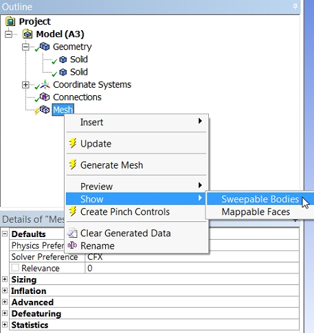
It is useful when you first open ANSYS Meshing to Right click on "Mesh" in the left-hand model tree and choose the option to “Show" -> "Sweepable Bodies”. Upon choosing this option, any bodies within your assembly that can be swept automatically will be shown in green on your screen.
If you expected that something should have been sweepable but it is not shown in green, then you may need to decompose the domain further such that any problematic bodies have a topology that can be swept. Often the problem is due to some small sliver surface or other area that is inhibiting the regular grid-like 'map meshing' of all side faces (along the direction of the sweep) which simply need to be cleaned up before this can occur. This can be done either back in DesignModeler, or using 'Virtual Topology' tools right here in ANSYS Meshing.
Once you are happy with the geometry, you can insert a sweep method by Right Clicking on Mesh in the Outline Tree and choosing to Insert -> Method. We then change the type to Sweep, and choose the body that we aim to sweep.
If we require inflation layers, which we generally do (and will discuss in a future post), then we choose the source face for the Sweep Method (or for additional control, both the source and target faces). This is required so that the meshing application knows explicitly which face to mesh first before sweeping this meshed cross section through the rest of the body.
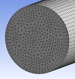
At this point, we can choose to create an initial mesh to confirm that the swept mesh can be created as expected. We can then apply additional face sizing and inflation to the source face and generate a final swept mesh for the body. You can see in the image below that the source face on the end of the cylinder has been meshed, which was then brought through the swept section at specified intervals resulting in a mapped quad (rectangular) mesh on the side faces of the cylinder.
If the mesh on the source face was also entirely composed of a quad surface mesh, then the entire mesh generated would be hexahedral. In this particular case, we have started with triangular surface elements on the source face (with quad elements in the critical inflation layer region), which results in a hybrid prism/hex mesh within the meshed volume. The advantage of this approach is that it will yield more accurate results than a full tetrahedral mesh, in a much shorter time due to a reduced total number of cells. This is particularly true in flow-aligned geometries such as internal flow through pipes or ducts with arbitrarily complex cross-sectional shapes.
In our next post, we will continue with our discussion on preferred meshing methods for CFD by looking at how to add Inflation Layers to your simulation. We'll discuss their importance to CFD accuracy, how to properly define them and explain the preferred settings. In the meantime, please contact our Support Team if you have any further questions on meshing for your particular applications.


