Mixing processes are involved at some level in nearly all manufacturing processes and are fundamental to the successful operation of a wide variety of applications. Some of the common processes where mixing is used in industry are for clarification, cell culture growth, fermentation, polymerisation and blending. These processes are found in a wide range of applications, such as the paint, food, pharmaceutical, minerals and water treatment industries. Huge budgets are spent each year on processes and technologies that allow improved mixing of two or more materials and many millions are lost because of non-efficient mixing due to poor product performance and reduced efficiency. This transformation process is depicted in Figure 1 below.
For this reason, process engineers around the world are now relying on computational fluid dynamics (CFD) to obtain detailed insights into the overall performance of their process equipment to develop methods by which they can predict when and how good mixing can be achieved. In addition to improving overall mixing performance and product uniformity, these efforts are aimed to:
- increase product and process quality,
- enhance vessel performance,
- increase throughput,
- reduce waste and
- drive down operating costs.
When tackling a mixing problem, typical questions include: What types of transformations are expected to occur? How fast will these transformations occur? What is the best way to carry out these transformations?
Mixing calculations involve the accurate determination of the advection velocity field, often the calculation of the motion of the particles of the material that has to be mixed, and an assessment of the mixing characteristics of the flow. This might sound like a daunting task, but luckily CFD analysis allows the user to obtain a detailed picture of the mixing behavior. CFD is a powerful tool for the modelling of mixing processes because it provides a method to link the process and fluid flow information. With ANSYS CFD, examination of single-phase flows in any arbitrary mixing vessel is now a routine task.
Solving Mixing Problems with CFD
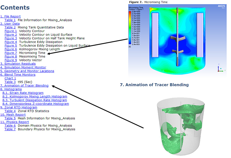
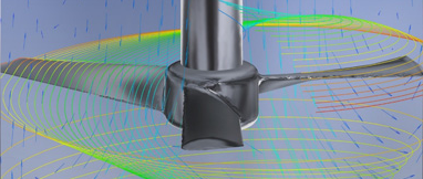
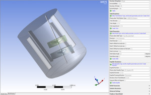
One of the most common mixing devices is a single- or multi-impeller agitated vessel with baffles. ANSYS CFD offers a new solution to modelling this type of vessel: a fully automated solution template where engineers input the mixing tank geometric parameters and operating conditions - the complete design analysis is then setup and solved automatically and a summary report is created which gives engineers immediate access to all the key parameters related to their mixing process. Figure 2 shows an example of the type of graphical outputs produced including the velocity vectors and representative streamlines within the fluid. Additionally, quantitative data such as Power numbers, Flow numbers and turbulence quantities are produced automatically by this template.

Figure 2. ANSYS automated tools allow engineers to accurately determine the flowfield within a mixing vessel. Courtesy ANSYS INC.
Multiphase Mixing
More experienced users can then readily extend this setup to multiphase applications. In the process industry, a typical process requirement is for a secondary phase to be suspended into a primary fluid phase for the purpose of dissolution, reaction, or to provide feed uniformity. If these vessels are not functioning properly, by inadequately maintaining suspension, the quality of the subsequent material processing can suffer. Associated with the operation of these units is a need to maintain the lowest possible cost. The challenge is in understanding the fluid dynamics in the vessel and relating this knowledge to improve the design. In these cases, CFD modelling provides comprehensive insight to both the multiphase transport and the vessel design parameters. For example, in wastewater treatment, the coagulation-flocculation stage is used to agglomerate suspended particles to produce flocs that are easier to separate by gravity (larger particle size equates to higher settling velocities). It is vital therefore to know the distribution of the particles in the volume of fluid and their respective velocities. These variables are notoriously difficult to calculate in a physical experiment, but by simulating several different configurations using CFD, engineers can easily determine the optimal configuration for their system to achieve efficient coagulation and flocculation.
Solids Suspension
Figure 3 below shows the predicted solids distribution in a tall vessel with a single and dual impeller system with a qualitative comparison of the solids cloud between an experiment and a CFD simulation.
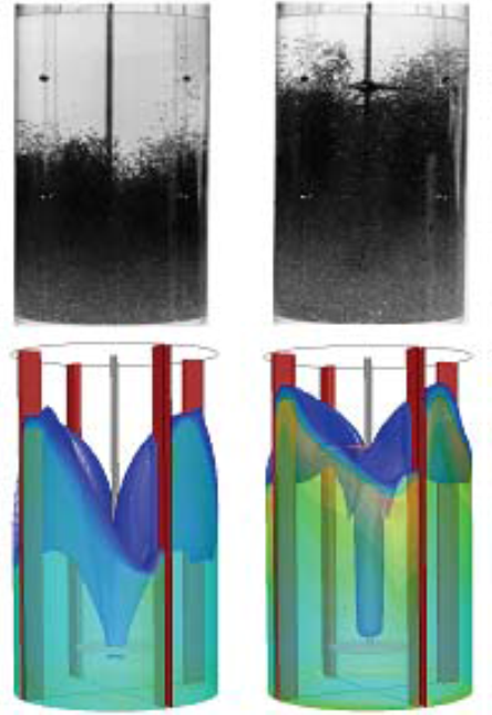
Figure 3: Suspension study - top images are from experiments and bottom set are from CFD. The impact of adding a second impeller is evident. (Taken from CFD modeling of solids suspensions in stirred tanks – Oshinowo, Bakker).
The results of CFD mixing simulations also provide invaluable insights into the distribution of suspended particles for various impeller configurations. This is clearly demonstrated in Figure 4, where CFD analysis involving solids suspension is validated against experimental test rig measurements.
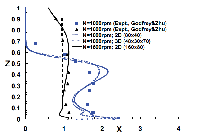
Figure 4: Axial concentration profiles of solids in suspension for various agitation speeds with an average concentration of 12%. X is the concentration divided by the mean and Z is the relative height. (Taken from CFD modeling of solids suspensions in stirred tanks – Oshinowo, Bakker.)
Scale-up and particle distribution are not the only key features that engineers can investigate by using CFD for mixing problems. ANSYS CFD allows determination of how time and length scales change with an increase in vessel volume, the distribution of energy dissipation and the effect on mixing quality as a function of the stirrer position. The velocities of the phases and the degree of mixing can be predicted with an accurate description of the turbulence, swirl and vortices generated in the mixer. CFD also allows engineers and vessel designers to run goal-driven optimization studies, for instance by manipulating the parameters for heat input into a tank to achieve a desired temperature profile. This optimisation process can be automated within the software, in contrast to multiple physical prototypes and experiments which can often be time consuming and expensive.
Transient Events
Another significant advantage of CFD analysis is its ability to forecast the behavior of mixing vessels during transient events such as the time required for a thermally stratified tank to reach a uniform temperature. Even longer timescales are possible when considering the likely lifespan of the plant, with the ability for CFD to couple with structural FEA to provide insight into the fatigue life of impellers and related equipment. This unique ability to couple ANSYS CFD software to ANSYS FEA fatigue calculations is conducted using the ANSYS Workbench and provides valuable engineering outcomes if designers can avoid the significant costs due to lost production and plant shutdown.
Minimising Erosion
Another multiphase mixing example involves the precipitation of alumina hydrate (used in the production of aluminium). In this and many other applications, the process uses tanks with solid particles that impact the impellers which wear out by erosion, meaning that the impeller must be changed before its operational lifespan is exceeded (leading to additional costs associated with component substitution and unscheduled plant shutdown). Typical erosion behaviour is shown in Figure 5 below. CFD studies have been carried out to analyse the interaction of various impeller designs with impinging alumina hydrate particles to identify areas of high erosion. This detailed information allows engineers to select the best impeller designs to minimize erosion and maximize the life of the equipment.
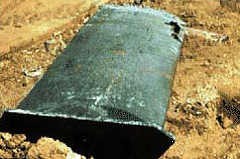
Figure 5. An impeller blade after four years' wear. Image courtesy of LIGHTNIN NY.
Each of these mixing examples highlights common uses of CFD modelling techniques which are helping companies around the world to balancing the business requirements of containing costs with increased customer demand for improved mixing speed and quality. Due to the complexity of mixing tanks (impellers, shafts, baffles, sparger, etc.), the implementation of a robust simulation methodology using the ANSYS CFD Mixing Template allows users to gain important insights into mixing performance and understand how equipment selection affects product quality. This automation of the CFD modelling reduces the time required to evaluate multiple designs, thus reducing the need for expensive physical testing, and ultimately reducing overall time-to-market and providing a higher return on investment (ROI). From an engineering perspective, the knowledge and insight gained from CFD provides a great opportunity for further product innovation, thus continually strengthening the competitive position of companies using CFD to study their mixing processes.
If you'd like to learn more about mixing, there is still time to register and attend ISMIP 8 – International Symposium on Mixing in Industrial Processes, 14-17 September 2014, Melbourne, Australia. Be sure to visit the ANSYS stand and also learn about the latest developments in equipment design and both experimental and computational techniques from the diverse international speakers. More details are available at http://www.ismip8.com/
More information on the ANSYS CFD Mixing Template can be found here at the ANSYS website.
- Mixing Template - example of automatic vessel geometry creation


- Mixing Template - example of automatic report generation