Home / Business Benefits / Solving Conjugate Heat Transfer problems

Solving Conjugate Heat Transfer problems


For many simulations of real world engineering applications, the predictions of heat transfer properties are as important, if not more important, than the actual flow field. Such scenarios include simulations of heat exchangers, HVAC (Heating, Ventilation and Air Conditioning), combustion/burners, electronics cooling, and many more. In these applications, we are often interested in how heat moves through both the fluid and solid domains, and importantly the transfer of heat across the interface between adjacent domains.

ANSYS CFD is a leader in solving all three modes of heat transfer: convection, conduction and radiation. Deciding which physics to include is critical to setting up an efficient CFD model. For instance, radiation provides a computational overhead but it is a very important heat transfer mode for bodies with high temperatures which radiate to cooler adjacent bodies or to a lower ambient temperature (since radiative heat transfer scales with Temperature4).

This image shows the heat that is convected away from a finned heat exchanger. As indicated by the streamlines, air is flowing from left to right in the image.

This image shows heat being convected away from a finned heat exchanger. As indicated by the streamlines, air is flowing from left to right in the image. The size, shape and number of fins can be easily optimized using CFD and Design Optimization techniques


Conjugate Heat Transfer (CHT) is applicable whenever there are two adjacent domains and we wish to analyze the heat transfer between these domains. These domains can either be solid or fluid domains. One example is the forced or natural convective cooling of a heat-sink attached to active electronics components which generate heat.

As well as heat-transfer across solid-fluid domains, we can also resolve heat transfer across solid-solid domains and fluid-fluid domains. Solid-solid interfaces are used where two solid components are in contact with each other and there is heat flowing between the objects. Although a fluid-fluid CHT system may seem unphysical, it is a valid assumption in some cases, such as a co-flow heat-exchanger where two fluids are separated by a thin wall. In this case, it can be assumed that the heat-transfer across the dividing wall is calculated in the wall normal dimension only (without explicitly meshing the wall thickness), and there is negligible heat flow along the wall.

In all of the above instances, a thermal resistance can be applied to the interface in ANSYS CFD. Such resistances can be used to represent thermal coatings (often used in electronics applications) or badly mated surfaces between adjacent solids (to understand the tolerance of poorly designed connections).


This image shows a cross-section through the stream-normal plane of a finned heat exchanger. Heat is input to the system at the bottom boundary condition and is carried through the structure and out into the surrounding air.

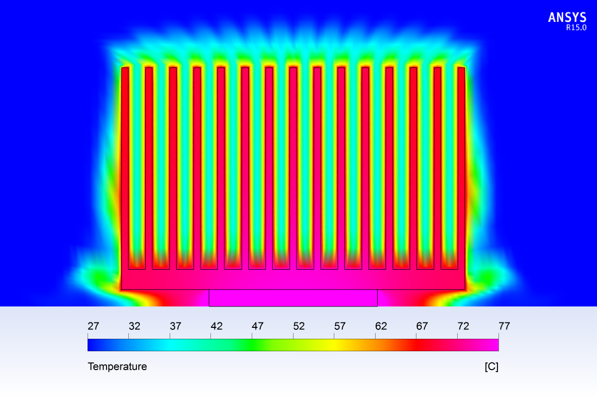
This image shows a cross-section through the stream-normal plane of the above finned heat exchanger. Heat flows into the heat sink from the active electronics components on the base and is carried through the heat sink fins and into the surrounding air.  The boundary layer is critical to this heat transfer and an appropriate near-wall mesh is needed.

For CHT simulations, it is critical to select appropriate boundary conditions that best represent the physical situation. ANSYS CFD provides a wide range of thermal boundary conditions, but also allows users to customise boundary conditions (using UDF’s or CCL Expressions) so that any heat transfer situation can be modeled.

One extremely important aspect of performing accurate CHT simulations is the wall adjacent mesh sizing, as accurately resolving the thermal boundary layer is crucial for producing reliable CHT results. To resolve the thermal boundary layer, an identical approach can used to when we are resolving the viscous boundary layer (for accurate flow separation, pressure drop, etc...), where we create high-aspect ratio prism or hexa elements stacked in the wall-normal direction (protruding into the fluid domain). Within the solid domain, however, there is no need to have such resolution (as there is no convection) so a uniform, coarser mesh can be used.

The use of Conjugate Heat Transfer simulation unlocks a range of simulations that can be performed using ANSYS CFD across industries including electronics, built environment and power generation. With proper training and knowledge, CHT simulations contribute an integral aspect of the Simulation-Driven Product Development approach that is being embraced by innovative designers and manufacturers worldwide. Contact LEAP today if you have an engineering problem where heat transfer is an issue.

10 comments

  • i like model conjugate H.T.

    inner fliud: compressed gas @ 1.47MPa , 355 k
    Middle solid pipe: aluminium
    Outer fliud: atm air

    but i'm gonna give heat flux b.c to outer tube wall abt 1000 w/m2

    pls i need b.c for inlet & outlet including backflow .

    and also solution algorithm ,

    when i'm simulating , inner fluid temp has to reduce but its increasing. pls help me

    • Dear Parkesh

      Perhaps reviewing your boundary conditions will indicate where the problem lies. The boundary between fluid and solid zones (or fluid and fluid zones if using a thin wall approximation in Fluent) must be specified to allow the heat energy to flow between the zones. In Fluent, this option is avalible under the "Thermal" tab of the boundary condition, and in CFX the option is in the Additional Interface Models tab of the Interface.

      In addition, double check the direction of your applied boundary conditions. 1000 Wm^-2 is adding energy into the system at the boundary (source) rather than removing the energy (sink). This would cause your model to heat up as you reported.

  • Could you please explain the temperature range at which radiation heat transfer is more important, or in general could you please describe on assessing the need to consider radiation in a CHT simulation scenario

    • Hi Ramesh,
      As a rule of thumb, radiation should be important if the temperature range exceeds 30[deg], or more importantly, if the expected heat flux due to radiation is comparable to the convective/conductive heat flux.
      Regards,
      LEAP CFD Support

  • I am an Engineering student of Mechanical Engineering and currently
    doing a project - Conjugate heat transfer analysis on a cylinder block
    of single cylinder IC engine in Ansys workbench CFX Pre.
    The cylinder block is placed in a fluid domain of air with inlet
    velocity(20-80 Kmph). I have applied a uniform temperature of 500
    degree celcius to bore surface. I want to analyse the effect of
    velocity on the heat dissipation through fins. I think I have to apply
    convective heat transfer coefficient to fin surfaces, but I am not
    able to understand how to give the value depending on the velocity. I
    have searched for correlations to calculate heat transfer coefficient
    but it requires the temperature difference of fin wall surface and
    ambient air which I do not know as fin wall temperature has to be my
    output result. Can I solve the problem without using heat transfer
    coefficient. Please help in me solving the problem.

    • A conjugate heat transfer project will need to have the cylinder in a fluid domain and use a velocity inlet to drive the external airflow at a specified temperature and velocity. Heat transfer coefficient boundaries would be appropriate on the fin walls if you were only interested in the solid temperature and had a good idea of the expected fin surface temperature (as you mentioned). However, based on the setup you have described and the desired output of the model, your model will be more successful using the fluid domain to apply external airflow. In fact, by using this method you can even have CFD-Post report the actual heat transfer coefficient values!

  • Hello, I am also doing CHT problem. The problem is that there is a cylinder with heat source inside lying in the fluid channel. Because the temperature of cylinder is too high(up to 1000K), the radiation needs to be considered. The fluid is a non-participating material. But now, I have no ideal how to set the radiative model, especially for the solid zone. All precisely, I have selected the coupled wall condition in the interface. What should I do for the radiative model?

    • Hi Shen,
      For information regarding the use of Thermal Radiation Models within ANSYS I would recommend taking a look at Section 12.4.2 for ANSYS CFX, or Section 13.3 for ANSYS Fluent of their respective ANSYS help manuals.

      You may like to look at the S2S option as a first point of call as this will assist in stabilising your simulation. From here you can look at whether your results are physical and whether you are able to refine your simulation further.

      Thanks,
      LEAP Support

  • Hi I just want to say you guys are amazing! I do have a question regarding CHC if you don't mind. For my undergraduate CFD semester project I have developed a transient conjugate heat transfer model of a centrifugally ventilated disc brake rotor to simulate the time dependent heat transfer during a hard braking scenario. Using methods of dynamics I calculated a heat power load for the front rotor during a 3 second constant deceleration. Using expressions, the inlet velocity was described based on the dynamics while the angular velocity of the rotating domain (rotor) was specified using the relationship between linear and angular velocity. My intention was to directly calculate the convection coefficient's from the fluid dynamics by using a two way close coupled FSI simulation via system coupling. Granted I am on the student license this was quite the challenge. The results I got were indeed better than expected and the flow visualizations were very cool. Unfortunately I did not have sufficient cells/nodes to accurately resolve the near wall boundary layer effects inside the rotor vanes (student license strikes again).

    My question is, is it possible to directly calculate the convection coefficient from the fluid dynamics without using a computationally expensive two-way FSI in system coupling and if so could you recommend a method for doing so either transiently or at steady state? It was my understanding that the mechanical and fluent solvers needed to transfer the data between each other in order to calculate the convection coefficient. Also the time dependent aspect certainly added unnecessary complexity but it was very interesting to see the evolution of the non-uniform temperature distributions and convection coefficients.

    Thank you,
    Chris

Leave a Reply to Ramesh - Cancel Reply

Your email address will not be published. Required fields are marked *