
In the field of wind engineering, LEAP has seen first-hand the rapid transition of CFD from academic curiosity to an established and well-validated methodology that is accessible to all engineers and consultants in the industry.
In Australia and New Zealand, ANSYS CFD continues to gain acceptance as a tool for wind studies involving façade loading and pedestrian comfort. Challenges are posed by complex urban geometries and the transient physics involved, but ANSYS has invested heavily in better pre-processing technologies such as ANSYS Spaceclaim and ANSYS Fluent Meshing, as well as the development of high-fidelity hybrid turbulence models, more robust numerics, and improved parallel scalability. Seamless coupling with ANSYS structural mechanics also provides a powerful toolset for the assessment of structural integrity and fatigue for building façades and similar structures.

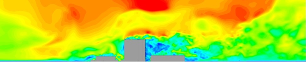
ANSYS CFD flow field over a complex urban environment
CFD simulation was previously viewed as a mere complement to traditional experimental wind engineering techniques (i.e. on-site, or reduced-scale wind tunnel tests). However, with these recent developments, CFD simulation now shows clear advantages in not being hindered by the similarity criteria in reduced-scale wind tunnel testing, and an ability to capture and report the full complexity of the turbulent flow-field (being unrestricted by the number of experimental gauges, unlike physical testing). Furthermore, the relative costs and faster turn-around time associated with computational simulation over traditional wind tunnel testing now makes it an extremely attractive option for wind engineering consultants conducting both early-stage conceptual as well as detailed design studies.

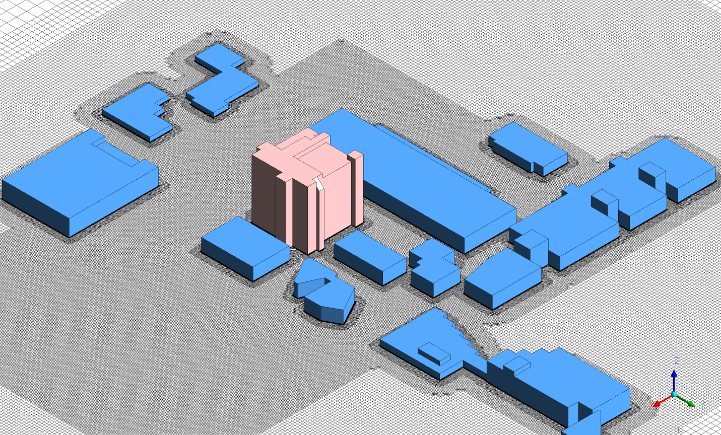
ANSYS Spaceclaim and Fluent Meshing used to easily model complex terrain effects
Importantly, ANSYS CFD also allows for the modelling of additional complexities that are influential but would otherwise be difficult or too conservative to include via reduced-scale wind tunnel testing, such as:
- Atmospheric boundary layer profile development
- Surface convective and radiative heat transfer and detailed solar studies
- Wind energy site assessment and real terrain modelling
- Wind-induced acoustics modelling
- Wind-borne debris
- Multiphase flow such as the transport and deposition of sand, dust, rain, hail, and snow.
For these applications, high-fidelity CFD simulations provide very detailed information on the relevant flow variables in the whole calculation domain, under repeatable operating conditions and without any issues of similarity/scaling constraints.
As an example, engineers at LEAP Australia recently contributed to the emerging body of work using CFD in wind engineering through a partnership with the RMIT University UAS Research Team. The team used high-fidelity CFD simulations of the flow over the Bundoora West campus of RMIT University to visualize regions of potentially high wind updraught regions to assist with Micro Air Vehicle (MAV) energy harvesting and flight sustainment.
ANSYS Fluent Meshing is used to generate a hexcore grid, resulting in a large percentage of isotropic hex cells for an accurate representation of recirculation patterns and wake effects
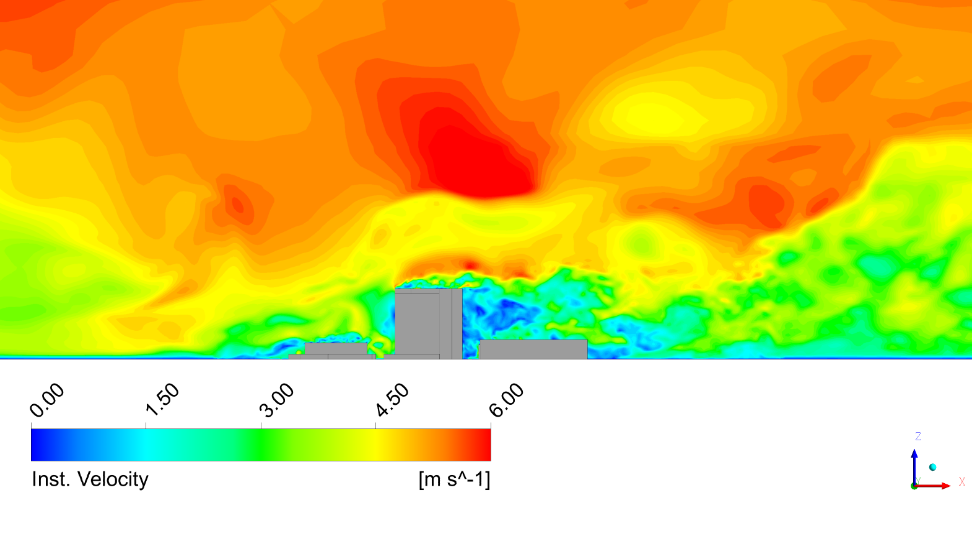
The Improved Delayed Detached Eddy Simulation (IDDES) in ANSYS Fluent is used to automatically generate vortical structures in the atmospheric boundary layer
The wind pattern was simulated computationally at full-scale using a hybrid Reynolds-Averaged Navier-Stokes (RANS) and Large-Eddy Simulation (LES) model. The advantages of this approach lie in the ability to resolve turbulent structures at the super-grid scale and to use empirical models for sub-grid turbulent structures, thereby allowing the modelling of large computational domains with the available hardware resources. While RANS simulations remain the method of choice and will continue to play an important role in wind engineering studies, the limitation of RANS turbulence models in capturing the inherently transient features within an urban environment (such as recirculation and vortex shedding) is already well known. However, with the continued increase in hardware performance and solver scalability, hybrid RANS-LES models have been developed which can accurately resolve broadband turbulent structures and frequencies at lower computational cost. In this example, the wind was represented via an atmospheric boundary layer profile and the terrain was modelled using an equivalent surface roughness. Full details of this work can be found in this paper in the Journal of Wind Engineering: (http://www.sciencedirect.com/science/article/pii/S0167610515000252)
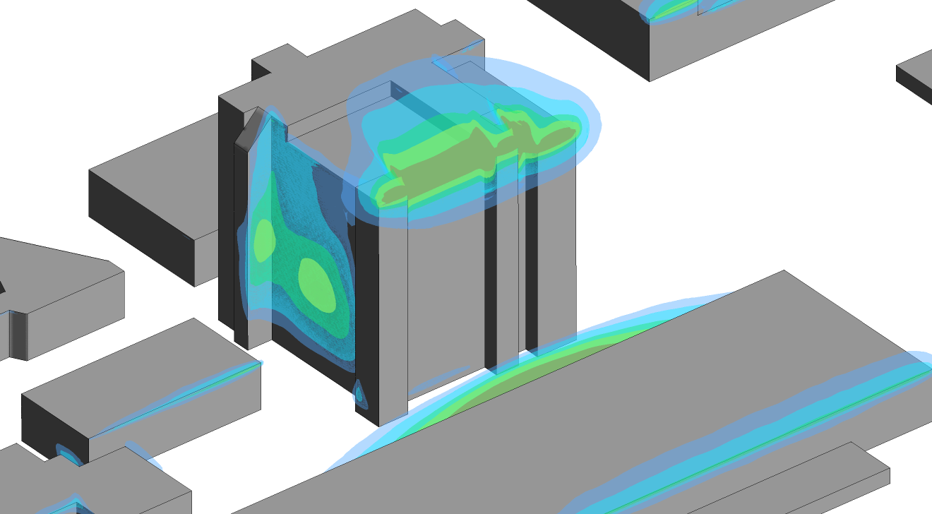
Regions of maximum updraught around the campus were identified and used to program a flight path / trajectory for the MAV
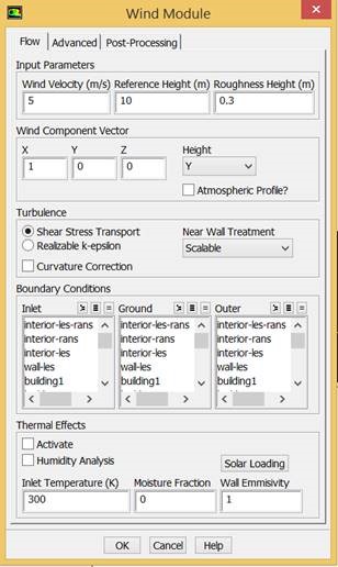
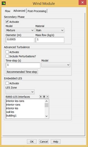
Example panels from ANSYS FLUENT WIND MODULE
Thanks to the customizable GUI available in ANSYS Fluent, engineers at LEAP Australia have also developed a streamlined and automated workflow for wind engineering studies (see above). The WIND MODULE accommodates many of the best practice guidelines and models required in an easy-to-follow workflow for new and existing users alike. This new WIND MODULE, combined with the increasing robustness and speed of ANSYS Fluent for handling large-scale complex grids of arbitrary quality, means that ANSYS is clearly the tool of choice for studies involving wind engineering and industrial aerodynamics.
Are you excited by what is now possible using CFD in wind engineering? Check out this video from the RMIT University UAS Research Team and contact us to learn more:


