Welcome to the first in LEAP's series of CFD Tips & Tricks blogs. The topics for this first series of blog entries will focus on the selection of efficient and appropriate meshing methods, mesh sizing and mesh controls in ANSYS Workbench Meshing. Meshing is one of the most important influences on CFD simulation accuracy, although it does not necessarily need to be the most time intensive. In our experience, our ANSYS CFD customers become more confident and efficient with meshing as they gain a better understanding of the importance of certain mesh settings and the likely effect of these settings on final solution accuracy.
Where to start?
After defining your project scope and the key variables of interest (either geometric and/or boundary/operational conditions), the first step is to prepare the geometry and create the fluid domain for the CFD simulation. The aim at this stage is to make sure that the geometry is as clean as possible before we create the fluid domain either in or around the body.
Within the ANSYS geometry products there are semi-automated cleanup options that can remove holes, spikes, sliver surfaces and other CAD related features that will cause meshing issues. Small details such as fillets or bolt heads are often insignificant details which can be assumed to have no impact on the final solution (especially in terms of a key engineering quantity such as lift, drag, max velocity, max temperature, etc...). Be careful and use your engineering judgement (in collaboration with your colleagues and team members) to ensure that you do not neglect geometric features which may have an effect on the physics or critical flow features!
To run the simulation we must take the clean geometry and discretise the fluid domain into a number of control volumes (often called cells or elements).
Firstly, we should remember that we want to capture the geometry with sufficient mesh resolution that we are solving for the correct shape of the fluid domain (ie. respecting the curvature of all geometry) and, secondly, we want to use sufficient mesh resolution to capture all key flow physics. This is especially true in regions where we know upfront that there are likely to be large gradients in key variables (for instance, nonlinear changes in the flow velocity in the boundary layer adjacent to walls; or rapid changes in pressure or temperature within a mixing zone).
With this in mind, when first generating a mesh for a particular design, it helps to visualise and/or draw a schematic of the problem which identifies the expected flow behaviour. Once you have run a simulation for a particular geometry, or a number of varying geometries, you will then start to develop an intuitive understanding of the fluid behaviour and more importantly, you will be able to recognise areas that do experience higher gradients in key flow variables. These may be pressure or velocity gradients, gradients of temperature or some other important scalar value. For more rapid variable changes, an increased number of cells (either through upfront mesh refinement, or mesh adaption) will be needed across that region in order to properly capture the flow behaviour without smearing the result unnecessarily (with what CFD analysts term discretisation errors).
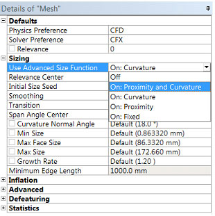
As you can imagine, gradients are likely to be higher near smaller features, wall boundaries, and curved regions. ANSYS has made our life easier by integrating Advanced Size Functions (ASF) into ANSYS Meshing which can do a lot of this initial work for us. These ASFs are used to automatically refine the mesh (with no user input required) using criteria based on local Proximity (between two or more surfaces) and Local Curvature of the original geometry.
In most cases, these controls automatically refine the mesh in the areas that would typically have higher gradients, so this is a really helpful tool for controlling the meshing of the domain with little user input. When using this tool (which I almost always use with both Proximity and Curvature turned on), users will have the ability to set maximum and minimum size controls at a Global Level, as well as important criteria such as meshing growth rates.
Advanced Size Function and Global Mesh Controls
This forms the basis of the automated meshing in ANSYS Meshing and allows even inexperienced users to generate a good initial mesh, especially when used in conjunction with some additional size controls and inflation meshing. The additional point/edge/surface or body specific controls all work with the Advanced Size Functions to allow users to create a smooth and quality mesh with defaults that are best suited to CFD solvers.
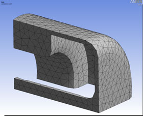
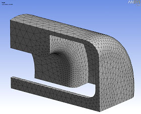
In the following examples, you can begin to understand the differences in the meshes that result from using the Advanced Size Function. The first example has purposefully deactivated the Advanced Size Function, and the second has used the Curvature control Sizing Function which has had the effect of automatic refinement in all regions of higher curvature.
No Advanced Size Function Used
Curvature Advanced Size Function
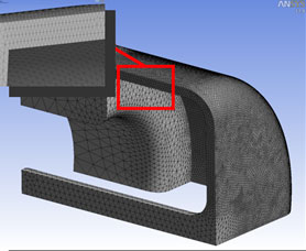
In the third example, we can see that with only the Proximity Control Sizing Function enabled, the mesher has sufficient refinement within the small gap, but has failed to capture the curvature that is just under the red box.
Proximity Advanced Size Function
By using both Proximity and Curvature by default, we have a much better mesh which adequately captures all the geometric features of this particular problem. In most cases, we would recommend this combined setting which will give you the best possible starting point and then allow you to further refine your mesh by implementing some of the local sizing controls that I’ll talk about in a later blog post.
Proximity and Curvature Advanced Size Function
The final Advanced Size Function option is the Fixed Option, which will apply a single mesh element size across the entire domain. We should note that this setting is not particularly well suited for most CFD applications, but does come in handy for some other ANSYS Multiphysics solvers.
Fixed Advanced Size Function
I hope that this overview of some of the Global Meshing Controls has been helpful, and please contact our Support Team if you have any further questions. In our next post we will look into the Local Sizing Controls that will allow us to further refine the mesh in areas of interest.


