
You may already know that Computational Fluid Dynamics (CFD) is currently used by all Formula One teams as part of their ongoing development for their aerodynamics and cooling packages. Since the technologies pioneered in F1 car development regularly flow through into other engineering industries, we felt that a post on this topic was the perfect way to launch LEAP's CFD blog.
[box type="info"] In recent years, CFD has become a tool that is no longer just a complement to F1 team's sophisticated wind tunnel and track testing equipment, but an indispensable tool for the top teams to gain that extra competitive advantage. In this post, we will focus on why and how this powerful technology is used by Formula One teams today, as well as global automotive manufacturers who employ similar techniques (within slightly longer timeframes).[/box]
Formula One is a unique sport from a technical perspective, where all teams manufacture and design components from a blank sheet to conform to a certain set of rules. These rules are interpreted differently by all teams and as such there is considerable design freedom (amid regular rule changes and updates). Ultimately, this design freedom has a significant impact on the performance of F1 car designs during on-track testing, qualifying and during real race conditions.
The aerodynamic design process must be extremely efficient for a team to remain competitive, as any inefficient period will inevitably lead to a loss of performance compared to other teams that have continued along an efficient development path. This is why supercomputers and wind tunnels run 24/7 at most Formula One team headquarters.
 Typical Formula One Super Computer
Courtesy of SAUBER PETRONAS Engineering AG
Most teams will adhere to the following development process.
- Initial CFD analysis of multiple concepts
- Further CFD development of the most promising concepts
- Wind tunnel tests of developed concepts
- Track confirmation of new parts (usually on the Friday before a race)
This whole process can be accelerated if the performance improvements are found to be significant enough, and potentially any idea (even relatively radical changes) could be designed, tested, and raced within just a two week period.
For an aerodynamicist, the use of CFD is a vital tool in Formula One, as it provides repeatable results in a controlled environment that is sometimes not achievable even in the controlled environment of a $200 million wind tunnel. The aerodynamicist has the freedom to design without limitations on mounting points, prototyping lag times or mechanical issues that may otherwise prevent physical testing. The increasing use of CFD has led to a process that encourages creative design and rapid development of concepts without these real-world constraints.
A wind tunnel is a great tool for determining the downforce and drag of a vehicle, but CFD is increasingly valuable as a complimentary design tool as provides the aerodynamicist with an additional understanding of exactly why a particular design provides superior performance, and provides insight into how a design can be further improved. Incremental geometry changes can easily be automated and CFD simulation rerun in batch, with interpolation of the results from the previous solutions to speed up CFD solver convergence. An added advantage is that this process occurs without the delays that are inevitably associated with prototype manufacture and wind tunnel scheduling (as well as issues with the wind tunnel model changing even in short periods of time as other beneficial parts become the new baseline).

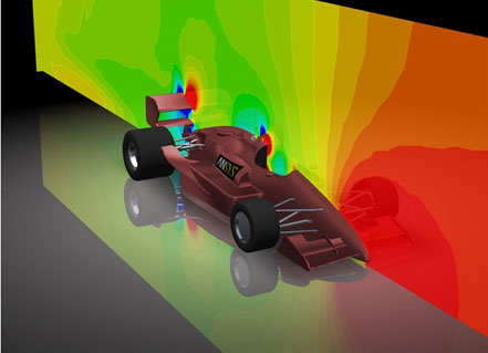
CFD Results on a Formula One vehicle
Courtesy of SAUBER PETRONAS Engineering AG
A Formula One vehicle is a complex aerodynamic device and there are a number of strong interactions between components on the vehicle. This starts at the front of the car where, in addition to generating downforce, the front wing starts to manipulate the flow around the tyres and over and around the vehicle. Extremely high fidelity solutions are required to ensure that the wake behaviour is accurately captured from the front wing (and all other parts), as these wake regions will be the onset flow for other areas of the vehicle, such as the sidepods and rear wing. These wake regions will also vary as the vehicle corners and sensitivity studies are undertaken to understand the wake behaviour and the effects on car performance. ANSYS has a range of highly-accurate turbulence models that are used to accurately capture these regions and ensure that the results across the entire vehicle are accurate and represent what is seen in the Wind Tunnel and ultimately during a race scenario.

Complex Wake behaviour at different Yaw angles
Courtesy of SAUBER PETRONAS Engineering AG
CFD is not only used for determining drag and downforce of a particular design, but it is also extensively used to develop intake and cooling ducts. Complex internal flow behaviour develops in these ducts and porous bodies are included to account for the effect of filters and radiator assemblies. These areas are a primary source of drag for the vehicles and due to their complex shapes can not be easily tested and developed in a wind tunnel. Brake ducts and the complex flow within the brake calipers and brake rotor are ideally suited to CFD development and this has led to the complex shapes and increased efficiencies that are seen in modern brake rotors. By developing these ducts using CFD, we can ensure adequate cooling or intake flow at a range of speeds and ensure that maximum efficiency is maintained.

Complex End Plates and Brake Ducting
Courtesy of SAUBER PETRONAS Engineering AG
A typical Formula One mesh will be in the order of hundreds of millions of cells and requires robust meshing algorithms to obtain the correct y+ values and ultimately the correct pressure and velocity profiles around the vehicle. The aerodynamicist then utilises post processing tools such as ANSYS CFD-Post or EnSight to generate a series of automated result plots, animations and reports, as well as key qualitative and quantitative results in key regions in order to understand how the behaviour of the newly added component has affected the flow around the rest of the vehicle. From this they can then redesign/optimise the component to give the desired effect, or move on to their next concept.
Without the use of CFD in Formula One, teams would be forced to return to the days of pure trial and error testing in a wind tunnel (based on educated designs/theory and prior experience). Our expectation is that this would significantly slow down the development rate of F1 vehicles and we would definitely not have the intricate shapes in F1 cars that we see today. All of these smaller seemingly insignificant twists and curls in the geometry are as a result of CFD and while each one may only have a small effect, over a complete vehicle the sum of these small contributions is often the difference between being on the podium or being relegated to the back of the field.
The images shown below highlight the subtle differences in geometry that will have an enormous influence on the flow behaviour around the vehicle. These images are from two sequential races that were held within a two week period. The upper image shows a simple flat plate being used for the lower outer surface, whereas the lower images has a multitude of curves and slots. This is typical of the design work that is carried out in CFD to optimise the geometry. These slots would have been developed in CFD by looking at their effect on the vortices that are present in this end plate region and their interaction with the complex wake of the tyre. The small changes here will have a big impact downstream, not only on the tyre wake as mentioned, but also on the flow to the rear diffuser and rear wing.

Front Wing Endplate variations between races
Courtesy of Formula One Tech And Art
CFD brings a level of understanding to these small design details that is simply not possible when working in a wind tunnel alone. The interactions in this region are so complex that a 2 to 5mm movement in a certain direction would render the whole development a failure. CFD allows the user to carefully tailor geometry such that the optimum amount of flow is distributed to the correct areas to have the desired overall effect. This effect may be to speed up or delay vortex burst, lateral movement of a vortex, or to develop new vortices to influence other components downstream.
The example above would have increased both front and rear downforce with a possible neutral or slight drag reduction. Each of these effects will have a tangible reduction in lap-times and make the vehicle more competitive on the racetrack. This is a great example of how CFD allows the aerodynamicist to innovate and push their design to the next level.
In summary, CFD has been critical to F1 car development over the past decade. Aerodynamicists within F1 teams can now visualise and quantify the effect of both small and large design changes without the associated costs and delays of manufacture and wind tunnel testing. This has led to increased throughput to the wind tunnel and ultimately throughput to the track of designs that are beneficial to car performance, which is reflected in the rapid pace of development in F1 cars in more recent years. Ultimately, this has had the expected effect of increasing the competitiveness of F1 teams that have been first to innovate using tools such as ANSYS CFD.
You may also be interested in hearing from some of the ANSYS CFD users at F1 teams such as Red Bull Racing. Red Bull has been using engineering simulation software since its inception to overcome the continuous design challenges of Formula One racing. "In the past, we introduced a design in March and maybe made two or three updates throughout the season," notes Steve Nevey, Red Bull Racing. "Today, the F1 circuit is so competitive that we're iterating new ideas all the time to suit different track configurations and driving conditions. If we stopped updating the car, we'd very quickly find our competitors passing us." Hear more from Red Bull CFD engineers, Steve Nevey and Craig Skinner, in an interview below:
Please leave a comment or question below if you have an interest in ANSYS CFD within motorsport. What are the most impressive design changes in recent years that you have seen come about through increased understanding of the flow around an F1 vehicle? Is your aspiration to be a CFD engineer within a F1 team? (We may be able to put you in touch with some useful contacts!). How could this kind of technology help you in your everyday engineering challenges?
References from:
Larsson T., Sato T., Ullbrand B. “Supercomputing in F1 – Unlocking the Power of CFD”, 2ndEuropean Automotive CFD Conference, Frankfurt, Germany, 2005
Formula One Tech And Art, Accessed: 1/12/11 http://formula1techandart.wordpress.com/2011/01/20/


