
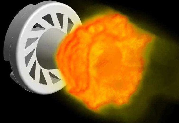
Combustion technology underpins almost every facet of our modern life. Electricity is generated by the combustion of coal, oil, gas and increasingly biomass. Cars, lorries and even lawnmowers are powered by engines that burn petrol or diesel. Industry uses gas-fired heaters in many processes to generate heat for applications as diverse as glass manufacture to calcination. All this is taking place in an environment where there is increasing social and economic pressure to minimise energy use, reduce pollution and protect the environment. As well as what we think of as conventional combustion there are many other applications of reacting flow in material synthesis, biochemistry etc. that can exploit the model developed for combustion. In this post we’ll be using the term “combustion” in a broad sense to represent any chemically reacting flow, some typical examples of which are shown below:

Examples of combustion and chemically reacting flows
It is straightforward to determine how much heat will be released by combustion of a given mass of fuel but this rarely provides sufficient information. Computational Fluid Dynamics models of combustion can answer many more questions than simple thermodynamics, including:
- Where will reactions take place and where is heat being released?
- What is the distribution of temperature and chemical species?
- What is the heat flux to walls, refractories, boiler tubes and other critical structures?
- What are the exit concentrations of pollutants such as NOx, SOx and soot? This knowledge allows us to implement intelligent modifications of the combustion system via simple procedures, such as air stagging or urea addition, with the aim of reducing pollutant formation.
- What modifications are required to a plant to change fuel, such as moving from burning pulverised coal to a mixture of coal, wood chips, organic waste, biomass or shredded paper? Does the change in fuel require a change in where/how fuel is injected? What is the impact on the changed operation mode on the temperature distribution?
- Will a newly designed burner be stable or will it be subject to flashback? What will be the metal temperatures?
To answer these and many more questions requires sophisticated state of the art CFD software. Both ANSYS FLUENT and ANSYS CFX are well equipped to model combustion processes, having not only the necessary combustion models but all of the ancillary infrastructure that is needed. The schematic below shows a schematic of the combustion modelling process. Essentially the conservation equations for mass, momentum, energy and chemical species are solved to provide local values of all of these quantities. High fidelity models for turbulence, thermal radiation and heat transfer are a requirement to produce accurate and reliable results. If solid or liquid fuels are present, then additional multiphase models are also needed to track the fuel particle /droplets and their history as they undergo the various stages of combustion.

Modelling of combustion processes
A key step is determining the approach to be used to model combustion. Essentially this depends on three important inputs:
- The configuration of the fuel and oxidiser. If they are mixed, then we have what is known as “premixed” combustion. If they are separate and the flame is located at the region where they mix, it is known as a “diffusion flame”. If some combination of both situations occurs, it is known as “partially premixed” combustion.
- Although combustion is a chemical process it may not always be the reaction rate that determines how fast a fuel burns. The ratio of the mixing timescale to a combustion timescale, known as the Damköhler number, determines the controlling physics. For large Damköhler numbers, it is the mixing of the reactants in a diffusion flame or transport of products in premixed combustion that determine the rate of consumption of the fuel. In all other situations the chemical reaction rate plays a role and finite rate chemistry models are needed.
- Once the above information is known, the next step is to decide the level of sophistication of the chemical kinetics to be used if finite rate chemistry is to be considered. Even a simple fuel, such as methane, requires a mechanism containing many tens of species and hundreds of reactions for a fundamental description. The decision has to be made if this level of sophistication is really needed or whether some form of reduced mechanism (containing only the most important reactions) or a single or several global mechanisms can be used (which rely on curves fitted to experimental data rather than being based on fundamental kinetics). This choice again affects which model is to be used and the computational resources that are required. If pollutant formation is important, then a more sophisticated approach is needed than just to model heat release.
The recent acquisition of Reaction Design by ANSYS means that the CHEMKIN suite of tools is now part of the ANSYS offering on combustion. CHEMKIN-PRO is used widely to develop chemical mechanisms and rapidly determine reaction behaviour in simple reactors (as shown in the figure below), such as perfectly stirred or plug flow geometries. There are also sophisticated tools in the Reaction Design suite to allow mechanism reduction and construction of reactor networks. There is also a coupling between ANSYS FLUENT and CHEMKIN that allows the stiff chemistry solver of CHEMKIN to be used by ANSYS Fluent.
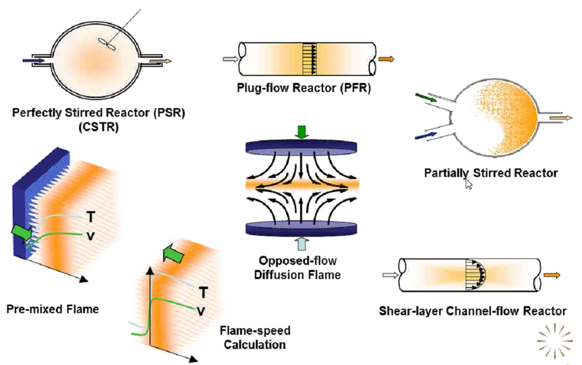
Examples of the reactors and calculations that can be performed using CHEMKIN-PRO
The above provides a very brief introduction to some of the considerations needed in the modelling of combusting/reacting systems using CFD software. Combustion is a broad topic and careful consideration of your CFD modelling approach is required for any given application, including key considerations of your project timeframes, available hardware and the most appropriate:
- Reaction model
- Dispersed Phase model
- Pollutant model
- Turbulence model and
- Radiative Heat Transfer model


