Home / Featured / Tips & Tricks: Estimating the First Cell Height for correct Y+

Tips & Tricks: Estimating the First Cell Height for correct Y+

Note: this is an old post.  The updated post series from 2020 is LEAP's 3-Part Series on "What y+ should I use in my simulations?" which is available here:

Old Post continues here:

In previous posts we have stressed the importance of using an appropriate y+ value in combination with a given turbulence modelling approach. Today we will help you calculate the correct first cell height (\Delta y_1) based on your desired y+ value. This is an important first step as the global mesh resolution parameters will also be influenced by this near-wall mesh as well as the Reynolds number.

Let's review the two main choices we have in choosing a near-wall modelling strategy:

Resolving the Viscous Sublayer

  • Involves the full resolution of the boundary layer and is required where wall-bounded effects are of high priority (adverse pressure gradients, aerodynamic drag, pressure drop, heat transfer, etc.)
  • Wall adjacent grid height must be order y+ = \mathcal{O}(1)
  • Must use an appropriate low-Re number turbulence model (i.e. Shear Stress Transport)

Adopting a Wall Function Grid

  • Involves modelling the boundary layer using a log-law wall function. This approach is suitable for cases where wall-bounded effects are secondary, or the flow undergoes geometry-induced separation (such as many bluff bodies and in modern automotive vehicle design).
  • Wall adjacent grid height should ideally reside in the log-law region where y+>11
  • All turbulence models are applicable (e.g. Shear Stress Transport or k-epsilon with scalable wall functions)

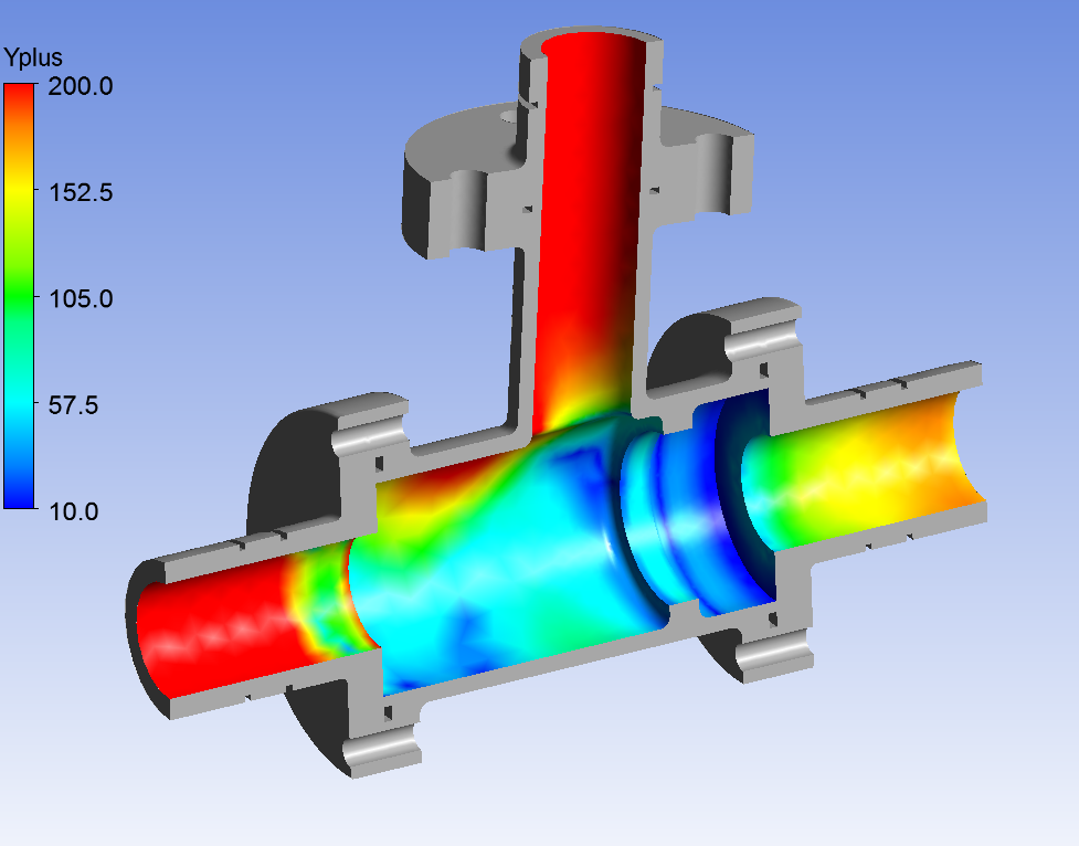
During the pre-processing stage, we need to estimate the first cell height ( \Delta y_1) so that our y+ falls within the desired range. The computed flow-field will dictate the actual y+ value which in reality will vary along the wall.  In some cases, we may need to locally refine our mesh to achieve the desired y+ value in all regions.


So how to calculate the First Cell Height for a desired Y+ value?


Firstly, we should calculate the Reynolds number for our model based on the characteristic scales of our geometry such that:

Re = \frac{\rho \cdot U \cdot L}{\mu},

where \rho and \mu are the fluid density and viscosity respectively, U is the freestream velocity, and L is the characteristic length (e.g. pipe diameter, body length, etc.).

The definition of the y+ value is such that:

y+ = \frac{rho \cdot U_\tau \cdot \Delta y_1}{\mu} \verb+ +\rightarrow \Delta y_1 = \frac{y+ \cdot \mu}{\rho \cdot U_\tau}

The target y+ value and fluid properties are known a priori, so we need to calculate the frictional velocity U_\tau, which is defined as:

U_\tau = \sqrt{\frac{\tau_w}{\rho}}

The wall shear stress, \tau_w can be calculated from skin friction coefficient, C_f, such that:

\tau_w = \frac{1}{2}\cdot C_f \cdot \rho \cdot U^2

The ambiguity in calculating \Delta y_1 surrounds the value for C_f. Empirical results have been used to provide an estimate to this value:

 Flow Type   Empirical Estimate
Internal Flows C_f = 0.079 \cdot Re^{-0.25}
External Flows C_f = 0.058 \cdot Re^{-0.2}


We can then input these known values into the above equations to estimate our value for  \Delta y_1.

When considering simple flows and simple geometry, we might find this correlation is highly accurate.  However, when considering complex geometry, refinement in the boundary layer may be required to ensure the desired y+ value is achieved.  In these cases, you can choose to re-mesh in ANSYS Meshing or use anisotropic mesh adaption (ie. adaption of local cells only in the wall-normal direction) to achieve your desired Y+ value across the entire model.  Please leave a comment below or contact our support line if you have any questions.

For the lazy CFD-ers out there, we have written an applet for you to estimate the cell height quickly.

89 comments

  • Thanks for so many Tips & Tricks. I learned a lot from your blogs.
    I have a question about the Y+. If the Y+ <<1.0 in my case and I used the scalable wall function, should I worry about that the prism layers can't cover the boundary layer(include laminar sub-layer and logarithmic region) rather than the wall function is right or not?
    Will you talk about the Enhanced Wall Function in the future? I expect that.
    Can you send me your spreadsheet that automatically calculates the 1st cell height to my E-mail? I appreciate that. Thanks again for your time!

    • The scalable wall function approach should not be confused with a magic method that displaces the prism layers to account for any initial bad judgement by the user when sizing the prism height. Rather, the scalable wall function is used when we have sufficient layers to capture the boundary layer, but we want to avoid the erroneous modelling of the laminar sub-layer due to the mesh being too fine. Such cases arise when we have varying velocity scales in our flow and we would like a consistent mesh resolution in the boundary layer first cell height.

      Let's consider the following example. If we have an overly conservative prism layer height in the boundary layer (i.e. first cell corresponding to y+ = 0.2) and we only have 20 layers then a low-Re model will fail to capture the entire boundary layer profile within the allocated prism layers and the boundary layer will in fact begin to grow within the tetrahedral region causing artificial restriction in boundary layer growth.
      https://www.computationalfluiddynamics.com.au/tips-tricks-cfd-estimate-first-cell-height/low-re/
      If we apply the scalable wall function to this model (using a suitable k-e approach) then a similar phenomenon will occur, with the exception that the first cell height is virtually displaced to a y+ value of 11.225 to avoid modelling of the laminar sub-layer (see scale of eddy viscosity ratio). The prism layers are not physically displaced, as this would incur re-meshing of the geometry at systematic iterations to ensure the exact y+ value is reached.
      https://www.computationalfluiddynamics.com.au/tips-tricks-cfd-estimate-first-cell-height/rke-scalable-wall-functions/

      The enhanced wall treatment for k-epsilon models is not a wall function to be precise, it is a methodology combining various wall functions. This is why it is referred to as a two-layer approach. If the mesh is fine enough to capture the laminar sub-layer (governed by the turbulent Reynolds number taking the wall normal distance as the characteristic length) then it will utilize the one-equation relationship to capture the sub-layer and transition to a log-law wall function for the turbulent region of the boundary layer. This approach is optional when using k-epsilon or RSM models in Fluent.

      The enhanced wall function is a blending function which combines a model for the sub-layer region and gradually blends to a log-law in the turbulent region. This method is the default option for all k-omega models in both CFX and Fluent. If the mesh is not fine enough to resolve the sub-layer, then the blending function will gradually blend to a pure log-law relationship.

  • Thanks again for these posts. They're extremely helpful. My question is how I would go about doing this for a rotating system (centrifugal pump)? Would there be different calculations for the rotating impeller and stationary volute?

    • Dear Tim,

      We're glad that you are getting value from the blog.

      The wall treatment is dictated by the relative velocity of the fluid flowing over a surface. The reference frame that the model is solved in does not have any impact on the turblence model as the relative velocity between the wall and fluid is Galilean Invariant. Before conducting your simulation, you will need to estimate the wall adjacent relative velocity. If, when reviewing your solved simulation, the boundary layer mesh was insufficient, you may choose to adjust the meshing parameters and solve the case again. For complex geometry such as turbomachinery, it is often difficult to initially estimate the velocities, and so you may not generate the most appropriate mesh on the first go.

      One consideration that you must take into account is the production of Turbulent Kinetic Energy due to swirling or rotating flow. With all turbomachinery, there will be a large component of primary and induced swirl in the flow field. In order to capture the additional TKE production from the swirl, it is highly recommended that you enable the curvature correction option for the turbulence model you are using. The curvature correction option is avalible for the following turbulence models in

      ANSYS CFX:
      Standard and RNG k-e models
      Standard k-o, BSL and SST models
      DES-SST & SAS-SST models

      ANSYS Fluent:
      Spalart-Allmaras one-equation model
      Standard, RNG, and Realizable k-e models
      Standard k-o, SST and Transition SST
      Scale-Adaptive Simulation (SAS) and Detached Eddy Simulation with SST (DES-SST).

  • Dear experts,
    I have some questions:
    1- When we use "Enhanced wall treatment" in Ansys Fluent, we should have ylpus of order of 1. Why? Does it resolve full boundary condition or just using wall function.
    2- You stated we should use y plus of order of 1 or more than 11. What about between them? for e.g yplus of 5. Then what does software do?wall function or full boundary layer resolution.
    3- About Spallart-Almaras model. What yplus should we have?
    And at last, could you please send me yplus calculator.
    Thank you very much for your useful site.

    • The enhanced wall treatment for k-epsilon models is not a wall function to be precise, it is a methodology combining various wall functions. This is why it is referred to as a two-layer approach. If the mesh is fine enough to capture the laminar sub-layer (governed by the turbulent Reynolds number taking the wall normal distance as the characteristic length) then it will utilize the one-equation relationship to capture the sub-layer and transition to a log-law wall function for the turbulent region of the boundary layer. The enhanced wall treatment is best utilized with a y-plus of one since it offers these scalable advantages over the standard wall functions (which best operates exclusively in the log-law region).

      If you are using a low-Re approach then a y-plus of 1-2 is ideally required to provide an accurate resolution of the boundary layer profile and accurately predict separation by adverse pressure gradient, heat transfer, etc. As we move towards y-plus values > 5 then we are entering into the buffer region between the sub-layer and the log-law region where neither law applies. For this reason it is advised to avoid resolving this area. However all ANSYS turbulence models are now essentially y-plus independent, and each model will provide a comparable resolution of the profile regardless of the first cell height.

      The Spallart-Almaras model now utilizes the enhanced wall treatment as per k-epsilon and RSM models. We should aim for y-plus values of the order of 1 to resolve the sub-layer and values greater than 15 for log-law treatment.

  • Dear Sir,

    In modelling multi-phase flow, we select the DPM model if volume fraction is less than 10-12%. So, my question is what is the basis and assumptions behind it.

    Thnaks & Regards,
    Prashant H

    • Dear PPrashant,

      I have just read your comment about modelling the multi-phase flow. So as I starting to simulate spouted-fluidized beds (it means that I have to simulate a flow containing two phases solid-air). My question is that you have said that if the volume fraction is less than 10-12% we can use the DMP model. My questions are:

      - Please can you send me reference papers where it is clearly said that less than 10-12% of volume fraction we can use DPM model for simulating a two-phase flow?

      - According to my knowledge, for reproducing accurately a multi-phase flows, we can use Eulereian-Eulerian or Eulerian-Lagrangian approaches. What is the criterium for selecting the first (Eulereian-Eulerian (E-E)) or the second (Eulerian-Lagrangian (E-L)) approach? I thnink that it depend on the solid diameter (if there is a limit of diameter above which the E-L is recommanded please pricise it) - Note that if you have some references to which you can direct me, It will be perfect for me.

      - I am learning that some of these various approaches are commonly named DPM, DEM, ... (the two names are those I only know and perhaps there are more). Please, if there are more can you specify them, and detail me for which approach (E-E and/or E-L) did they belong?

      Thank you very much

      Cherif

  • First, thank you for your tool which can automatically calculate the 1st cell height. It's very helpful.
    Second, I have another question for you. When I simulated a case with a very complex geometry, it was very hard to get a suitable mesh because of various velocity on the wall. You suggested to use anisotropic mesh adaption. I knew that fluent has the function of adapting mesh. But I want to know how to use anisotropic mesh adaption to adapt the local cells only in the wall-normal direction. I'm appreciate that you can teach us. It would very helpful for my simulations. Thanks for your time!

    • We are glad you have found our website so useful. You can stay up to date with future content by adding our RSS feed: https://www.computationalfluiddynamics.com.au/feed/

      We would suggest that you first complete Tutorials 3 and 6 from the Fluent Tutorial Guide to familiarise yourself with performing standard (isotropic) mesh adaptations. You can then find all the information necessary for performing anisotropic adaptation in the Fluent User's Guide in Section 29.9.

      It will be beneficial to practice anisotropic mesh adaptation with different settings on a simple mesh before applying it to your complex problem. Ensure that you inspect the mesh before and after the adaptation so that you understand exactly what is happening to the mesh; this way you will be confident when applying it to your full model.

    • I am now working on enhanced wall function, so I would like to ask you if possible to get your tool which can automatically calculate the 1st cell height. I think that it will be very helpful for me to getting the 1st cell height.

      Thank you,

      Cherif

  • Hi,

    thanks for your blog. It is very insightful.
    I have two questions:
    1. Is there any publication that describes your approach? I am doing my thesis and I need to quote a publication if I use those formulas.
    2. When I want to resolve the boundary I need at least 10 nodes in the boundary layer. How do I calculate my boundary layer thickness?

    Christoph

  • Thanks very much for the clear and profound explanation. Could you please also tell us how to determine the boundry layer thickness?

  • Hi,

    This site has some great topics about CFD so first of all thanks for the sharing of knowledge! Im still a beginner with CFD but i have learned a lot theory thanks to this site especially about turbulence.
    Most of my cases consist of oil/gas separators in which the overal flow pattern are of interest. My question is maby more fluid dynamics related, but what influence does the boundary layer on the results in terms of flow distribution? In other words is it really always required to create inflation meshes of 20 layers? I could imagine it is very important if you need to know e.g. a pressure drop, but maby not for cases where only flow distribution is of interest. Im asking because meshing 20 layers in acceptable queality and mesh size is almost impossible for my cases. Currently i use two layers with the realizable k-e model (enhanced wall functions) to have atleast consistant mesh size neer the walls.

    I hope you can enlighten me a little on this!

    Daan

    • You can keep your mesh coarser if you are modelling the wall behaviour with a wall function, such in cases where you have no flow separation at the walls. 20 layers are necessary if you want to resolve the BL and accurately predict the location of flow separation. We suggest you try both approaches on isolated components from your system and use the test results to review the actual fidelity requirwed for simulating the entire system.

  • LEAP Team;

    Thanks for this Blog, i'm new user of the Ansys CFD and with this Blog i'm learning a lot.

    Can you send me your spreadsheet that automatically calculates the 1st cell height to my E-mail?.

    • Determining the number of layers is dependent on the boundary layer thickness. In areas where there is still a high velocity gradient we should be aiming to continue the growth of prism layers, as the velocity gradient tends to zero and the velocity approaches the freestream we can begin our transition to tetra elements. You can estimate what the boundary layer thickness is likely to be from empirical formulations however these are generally restricted to zero-pressure gradient flows and therefore do not offer much assistance. We suggest that you look at our blog concerning boundary layer resolution and post-processing ( Turbulence Part 4 – Reviewing how well you have resolved the Boundary Layer). We offer some guidelines in this post for determining whether the inflation mesh has captured the boundary layer thickness appropriately.

  • I am doing simulation of centrifugal pump rotor 3000 RPM. can you tell me what would be the apprx Reynolds no ?

    I am considering the avg of blade width and distance between blades as a length (L) or as (hydraulic diameter) in order to calculate Re. (rho * v * L)/ mu..

    is it ok.?

    thanks

    • Hi, there are many ways of calculating the Reynolds number for a centrifugal pump geometry, for the purposes of determining the y-plus we are more interested in picking up trends as we scale the first cell height rather than determining the absolute value. Generally to determine the Re we take the characteristic length as the diameter of the impeller (D) and the characteristic velocity as the ratio between the D and the rotational speed (rad/s).

  • Are they any guidelines for Y+ when using a Roughness value or is the approach the same as that of a smooth wall? I am using SST turbulence model and the application is Turbomachinery. How robust is SST with Roughness?

    • The guidelines for y-plus when considering rough wall treatment are very different. For rough wall treatment the law of the wall is shifted by a factor related to the sand grain roughness. It makes no sense to have a cell height which is smaller then the defined roughness height as the roughness is "virtually" simulated through a modified law of the wall. It is considered best practice to have a cell height (y-plus value) which is twice the size of the roughness height. However this suggests that for larger roughness values we will sacrifice mesh resolution which is undesirable. In ANSYS CFD it is assumed that the roughness has a blockage effect, which is about 50% of its height. The wall is thus shifted or scaled to a value of (y+ = y+ + K+/2), where K+ is the non-dimensional roughness height. This function is similar in concept to the scalable wall function, but applied to rough walls. This scaling has been fully integrated into the SST model (because of its favourable automatic wall treatment) as of ANSYS R14. Much validation of the SST model was inspired by the turbo-machinery industry, for rough wall treatment as well as transition modelling. The two models work very well together with the SST base RANS model and might be something else to consider for your simulations.

  • Hello,

    I have a little bit complex geometry. A perforated pipe surrounded by loose aggregate and water enters through the aggregate into the pipe. I want to study the effect of wall roughness on flow. What is the free streaming velocity ? How can I determine this?

    I am new user of Ansys Fluent. So this might be a lame question but I need it 🙁 .Thanks for your help.

    Regards,
    Tanjina

    • Hi Tanjina, for the problem you've described this is likely to be an iterative process. You can start with an estimate of the likely fluid velocity based on the porosity of the aggregate, the flow rate and the open area in between the aggregate particles that the fluid will pass through. You can also calculate a similar velocity estimate for the flow through the perforations in the pipe itself. These estimates will be enough for you to create an initial mesh with a suitable first cell height in various sections of your domain, after which you can review the actual velocities calculated in the converged CFD results and actual Y+ values and then adjust as needed.

  • Thank you for your blog.
    Could U send me your spreadsheet that automatically claculates the 1st cell height to my e-mail?

  • Thanks alot, it was quite informative. May I ask that achieving the y+ equal or less than 1 is necessary when we are doing experiment on the Reynolds of the 1800 or something close?

    • At a Reynolds number of 1800 how sure are you that the flow is even turbulent? In some experimental validation cases, it is not uncommon to see y-plus values less than one – and for capturing certain physics, i.e. separation bubbles, boundary layer transition, etc. it is necessary to have such a fine resolution near the wall.

  • Dear,
    I performed the CFD simulation for the rod bundle using a standard k-e model with wall treatmet of 3 layers. Of results, the results of the corner and side channels facing the outer wall have not a good agreement compared to the experimental results. But, typical channel has a good agreement. The corner and side channels are a quarter and half of typical channel, respectively. What is the reason?

    • There are a number of reasons why your CFD results may not correlate with your experimental results. We suggest you closely review your choice of turbulence model (i.e. the use of realizable k-epsilon is advised), your grid resolution and type/location of inlet boundary condition. Performing a mesh independence study will be key for experimental correlation.

  • Hi, i have varying velocity scales in my scenario, i am using hex mesh, the domain is about 120 square meter (not a square), i need an inflation layer of 0.0007m to bring down the inflation layer to less than 5 (to avoid 5-30 region). By doing so i get inflation <<<1 at few places, is it fine working within this range of yplus with enhanced wall treatment. as i am using a small size inflation layer i get a high aspect ratio of less than 100, is it fine? what max aspect ratio i should aim for? If Ansys fluent is not sensitive to Yplus why should i use inflation and worry about Yplus? is inflation not required for Hex mesh?
    So many questions:-)
    Thanks

    • Dear Tariq,

      Given the extents of your model, it seems that you are doing some sort of environmental simulation. For these types of simulations, often the ground boundaries are not smooth walls, and have an inherent roughness based on the material (e.g. grass, asphalt, forest). It is important to include this roughness, as the wall roughness dictates the boundary layer profile on the ground. Rough walls require special treatment as opposed to smooth walls, and I recommend that you read some of the publications by Professor Bert Blocken, especially "CFD simulation of the atmospheric boundary layer: wall function problems" by Blocken, Stathopoulos & Carmeliet.

    • A hex mesh is already aligned with wall bounded flow and therefore already serves one of the purposes of inflation layers. With regard to first cell heights, you could control the level of boundary level resolution with inflation layers or simply through appropriate sizing of the hex mesh.

  • Hi,

    Thank you for your posts, they have been very helpful in getting started with CFD. Could you please send me the Y+ spreadsheet.

    Thanks,
    Dustin

  • Hi,

    I must say this is one of the best sites providing information on CFD basics. Appreciate your effort guys. Thank you!

    I am applying a k-w SST model on an unsteady flow past a two dimensional cylinder with diameter 0.15m (Reynolds number 15000, fluid is water, flow speed 0.1 m/s). With the formula given I have calculated the distance to the first node from the wall to be 0.15 mm to get a value of y+ = 1. Accordingly I created a region around the cylinder with this thickness and meshed it with 15 layers using edge bias option. What should I do with the area outside this thickness. Is it regular meshing with a smooth transition?

    The log law is applied to the region with y+ >30 while the law of the wall to the region with y+<5. What about the region in between these two values?

    I did check my y+ value in ANSYS post and it gives me values in the range 0.003 to 0.007. Should I be concerned?

    Thanking you guys again for this wonderful site,

    Anup

    • Hi Anup,
      For a two-dimensional cylinder you can apply mapped face meshing using a very simple multi-blocking strategy, with mesh edge biasing towards the cylinder to provide greater resolution near the wall. For more complex geometries, you can apply hybrid tetrahedral strategy, with prism layers near the wall and smooth continuous growth of tets in the freestream. If your y+ is that low then you have too many cells for your operating conditions, You should consider increasing the first grid height by several orders of magnitude to ensure y+ of the order of 1, and ultimately that your boundary layer does not grow in the tet region. The region in between the log law and the laminar sub-layer is known as the buffer region, where the flow exhibits a quasi-'transitional' behaviour where it has both log law and sub-layer characteristics.
      Regards,
      LEAP CFD Support

  • Oh! I forgot...what happens if y+<1 during calculation or after refinement (as far as I know FLUENT can't perform mesh coarsening) so, in this case I have to remesh my model? Thanks again

    • It’s certainly allowable to have a first cell height of y+<1. The important thing to regulate will be that you retain the number of layers you desire across the boundary layer itself. Fluent can coarsen using the same tool that allows refinement: Mesh Adaption.

  • Hi Leap Team,
    Thank you for helping us out by providing valuable basic informations on CFD.
    Please send me the y+ spread sheet.

  • Hi,

    I found your web site very interesting, thanks. I am wondering about the appropriate Yplus to be chosen for a DES-SST simulation of a compressible turbulent boundary layer flow.

    Thanks in advance,
    O.Marc

    • A DES model will require full resolution of the boundary layer, and therefore requires the first cell height to be y+<=1.

  • Hi Leap team

    Can you just help me in simulating the atmospheric boundary layer of wind flow around tall buildings in Ansys CFX.

  • Hi CFD experts..

    I am trying to simulate motion of a ship in both calm and irregular wave conditions with a forward speed. For getting a desired wall y+ value I calculated the near wall thickness.The prism layer thickness is put as turbulent boundary layer thickness.Are these things enough to get a desired y+ value..?

    In my model, there are several parts whose dimensions are lesser than my calculated prism layer thickness.Will that be a problem..?

    What is the y+ spreadsheet you people having..?...Will it be useful for me..? If yes, please forward that to me also...

    Thanks a lot...

  • Hi CFD team..

    I have read the posts above and I feel that the Y+ spreadsheet will be useful for me.Can you please send it..?

    Thanks and Regards

    HARIHARAN

  • Hi,
    I'm studying mechanical engineering and for my upcoming masterthesis i'm doing some research for cfd. Right now i'm trying to get some informations for this y+ -thing and going threw your 'tips & tricks'. Youre blog is really helpful so far, thank you 🙂
    I would be really interested in your spreadsheet you mentioned here. I appreciate that and keep up the good work!

  • Hi Leap Team,

    I'm trying to study the flow in a cfb riser with the realizable k-eps and scalable wall functions. I prefer to use a model for the turbulent effects and the sudden expansion from the feed. After verifying the y+, I was having values close to 2-6, why the difference?

    Thanks

    • The scalable wall function actually virtually shifts the first cell height to y+=11.067 for any cell with a height less than that value. Any mesh refinement that produces first cell heights under that value will have no effect on the final results due to the virtual shifting. Post will still calculate the values for your actual cell heights however, which is why you are finding y+ values in the 2-6 range. This should not come as a surprise as any calculation of y+ prior to solving is merely an estimate. If you desire to resolve the boundary layer, the k-e model with the enhanced wall function would be an appropriate selection, with the k-w SST being an even better selection due to its improvements over the k-e family.

  • Guys I am new in cfd so I have this basic doubt and badly need your help.
    I am doing an external aerodynamics problem, so for a given value of wall y+ how do I calculate the total boundary layer thickness to accurately capture the boundary layer?

    • Any fluid dynamics textbooks will have equations to calculate boundary layer thickness for a range of flows. In addition, there is a great discussion in Section 12.2.3 of the CFX Reference Guide regarding meshing with respect to boundary layer thickness.

  • I implemented this method to estimate my first wall-cell height for a y+ of 1 but when I checked the y+ in the turbulence contours in ANSYS fluent after the simulation converged, it showed a y+ of 387. I am not sure what exactly is going wrong in the process. I'm simulating an axisymmetric 1 shock intake with a cowl at Mach 6 flow conditions. I also used NASA Viscous Grid Calculator which verified my single line spacing. Would you know if there is a specific parameter that the y+ value is very sensitive towards?

    • The actual y+ values cannot be known until the solution has converged. It is quite common to need to adjust the mesh after inspecting the values from an initial solution as the values will nearly always differ from the estimate. Usually the variation in values is not as extreme as you are reporting, but with compressible flow the fluid density will certainly play a role as well as the near wall velocity. Our recommendation would be to alter your mesh according to the results from your first converged solution.

  • Hello,
    First, thank you very much for the very clear explanation.

    I calculated the first cell height myself with the same equations and I get exactly half of the value which the applet calculates.
    Did I forget to consider something or why do I get half of the value?

    Kind regards,
    Benjamin

    • Hi Benjamin
      Fluent is a cell centered code, y+ is evaluated at half the cell height (hence, a factor of 2 as you pointed out). CFX is a node centered code and evaluated at the node location, the value is not scaled as a result.

      Hope this clarifies your doubt.

      Regards

      LEAP Support

    • Hi
      Are you sure about CFX and Fluent difference of a factor of 2. I have ANSYS Fluent training slide on "turbulence models", they calculated the y+ same as the CFX results in the applet, but for ANSYS Fluent too.

  • Hi, I am new to CFD. Thank you LEAP CFD team for explaining wall functions. i would like to know the yplus value to be maintained for conjugate heat transfer analysis and which turbulent model can give results close experimental results . if you help me out, i am very thankful to you.

  • Hello Leap Support,

    In my project, I am looking at temperature distribution in a room which has an air inlet and exhaust with known velocity. I know the properties of the air such as density, dynamic and kinematic viscosity. However, I am not sure what should be my length scale to calculate Re. Dimensions of the room is known.

    I appreciate your help and support. Thank you.

    Regards,
    Dharav B

    • Hi Dharav,

      As your geometry has largely changing characteristic lengths (for e.g. the inlet diameters compared to perhaps the length of the room); I would be using a characteristic length that you know to come up with a baseline Reynolds Number. This can then provide you with a basis for the type of flow that is entering the room.

      Having turbulence switched on is the general approach as most regions will contain some regions of turbulent flow; however, setting up a base case and evaluating how accurate your simulation is, will provide you with a great platform to build off.

      Thanks,
      LEAP Support

  • Hi Leap team

    Can you help me in simulating the atmospheric boundary layer of wind flow around tall buildings in Ansys Fluent.

  • Hello!
    I want to create inflation around tubes of a shell and tube heat exchanger, I don't really know how to approximate the velocity around the tubes i just know the inlet velocity of the fluid (in shell side) for identify the height of first cell .

    Thanks for your help.

    Regards,

  • Late to the party, I see, but I would like that applet you mentioned, if it is still available. In any case, very specific and helpful info, thank you very much.

  • Noorlina Mohd Zanuddin

    Dear Leap team,

    The information above so good, clear and useful. However, the skin fraction formula given is flow in pipe n external flow for flate plat . Can I used the external flow skin fraction coefficient formula as above (0.058Re-0.2), if my model is external flow perpendicular to cylinder geometry?

    Thanks

    Regards,

    LINA

  • Hello,

    I see that I am very late to the discussion. I hope the application is still availbale, I would love to have it. Very good explanations thought. This site became my reference in matter of CFD simulations. Thanks a lot.

  • Hello Team LEAP CFD, thank you for this post. Would you please send me the first cell height calculator ?

    Thanks a lot

Leave a Reply to Christoph - Cancel Reply

Your email address will not be published. Required fields are marked *