Home / Tips & Tricks / Tips & Tricks: Inflation Layer Meshing in ANSYS

Tips & Tricks: Inflation Layer Meshing in ANSYS

Throughout our first set of Tips & Tricks posts relating to meshing controls and meshing methods, we have made mention of Inflation Layers a number of times.  Let's take this opportunity to explain exactly why inflation layers are a critical component of a good CFD mesh and how we can create them easily within ANSYS Meshing.

In our first posts on Mesh Sizing we explained that as well as capturing all key features of the geometry (using local sizing and the curvature size function), we also need to have a sufficiently fine mesh to adequately capture regions where the flow will experience rapid change in key variables such as pressure, velocity or temperature.   This initially led us to a better understanding of how we should apply Global and Local Mesh Controls.

Now, if you think about moving a probe from the freestream flow towards one of the walls in your fluid domain, as you approach the wall you will notice that the velocity decreases non-linearly up to a point where the fluid will have zero velocity at the wall.  This is what is termed the "no slip" wall condition in CFD.

If we plot a typical velocity profile in the near-wall region, we can see that we have a large change in velocity in the wall normal direction and it is important to our CFD simulation that we capture this gradient correctly.  To do this, we need to use inflation layer meshing to accurately capture the boundary layer region for any wall-bounded turbulent flows.  The image below plots the non-dimensional velocity versus the non-dimensional wall normal distance, with each line from top to bottom demonstrating the difference between a favourable pressure gradient through to adverse pressure gradient with flow separation.  It is clear that the flow behaviour in the near wall region is fairly complex and needs to be captured appropriately to have any confidence in our CFD results, especially if we intend to report key engineering data such as separation points or pressure drops.

Near-wall velocity profiles

Near-wall velocity profiles

Providing a suitable inflation mesh for the geometry is strongly tied to the choice of the turbulence model, and the flow field we are interested in capturing. We can elect to resolve the complete profile of the boundary layer of alternatively we can make use of empirical wall functions to reduce the cell count (see our post on turbulence modelling and wall functions). If we refer to the images below, on the left hand side we observe that the boundary layer profile is modelled with a reduced cell count, which is characteristic of a wall function approach. On the right, the boundary layer profile is resolved all the way to the wall. This will provide a more accurate resolution of the boundary layer. For certain simulations such as flows with strong wall-bounded effects, this resolution is absolutely necessary. For other simulations, the added computational expense is not always justifiable.

wall functions

Representation of Wall Function approach vs fully resolving the boundary layer

At this point, we begin to understand that the placement of the first node in our near-wall mesh is very important.  We use a non-dimensional distance (based on local cell fluid velocity) from the wall to the first node, which we term the y+.  To use a wall function approach for a particular turbulence model with confidence, we need to ensure that our y+ values are within a certain range.  This topic is covered in detail here

y+ definition

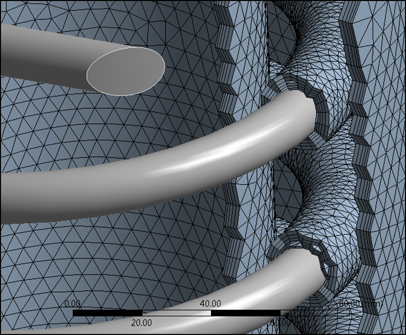
This topic will also be discussed more in a future post, but in general it is considered good practice to include between 10 and 15 inflation layers situated within the boundary layer of your flow to accurately resolve the boundary layer and accurately predict any separation or reattachment points.  So now that we understand the importance of inflation layers to our CFD mesh, how can we set them up?

Inflation Layer setup and options


For a 3D body, we begin by choosing the body (typically a fluid domain) that we want to create the inflation mesh within, and then identify the faces that we want to inflate from.

For a swept body, we begin by selecting the source face, and then the boundaries or edges from which we wish to inflate.  This is a different approach from other 3D bodies as the source face is meshed first individually, which is then swept through the body.

Once we have specified these boundaries to be inflated (either surfaces or edges), then it is easy to define the number of inflation layers, inflation growth rate and select one of the following methods: Total Thickness, First Layer Thickness, First layer Aspect Ratio, Last Layer Aspect Ratio or the Smooth Transition option (which uses a ratio based on the local surface mesh size).

As I mentioned earlier, we find that the First Layer thickness option is the best place to start, especially when you are trying to achieve a particular y+ value as this value can be parametrised in ANSYS Workbench so that any changes to the First Layer Thickness parameter will be proportional to the y+ values that you expect in your solution.  The first layer thickness that you choose should be used to obtain the correct y+ value for the turbulence model and flow behaviour that you are dealing with, which we will discuss in a future post.

If you have any questions related to this post or you would like some advice for your own inflation meshing, then please post a comment below or alternatively contact our LEAP ANSYS CFD Support Team.

60 comments

  • What are the best practices if we have 2 inflation layers (different initial height and number of layers) from 2 different surfaces ( like wheel and road) intersecting and the resulting contact is producing highly skewed elements?

    Btw, nice article.

    • Thanks for your question Vicky. You are correct that the intersection of a curved surface with a straight surface at an inverse tangent (such as the contact of a wheel with the road) has the potential to cause highly skewed elements due to both faces collapsing to an infinitely sharp angle. In ANSYS Meshing, one approach involves using the pinch tool to remove this problematic junction. A second approach which is likely to achieve a higher-quality mesh involves slicing the curved surface before it makes contact with the ground and extruding a block geometry from the sliced face to make contact with the ground. That way, we have a small surface with an angle of 90 degrees between the wheel and tyre which should not significantly affect the flowfield but allows us to produce a mesh of very high quality in this area. The slice should be offset from the junction by a large enough distance to ensure inflation layer continuity between the ground and the wheel, but not too large that it will affect the flow field. Furthermore, whenever there is a scenario that we have surfaces in close proximity and the inflation layers will collide, we find that we can achieve higher mesh quality by setting the collision avoidance option to ‘layer compression’ in the inflation advanced options panel.

  • Sir, is it possible to generate inflation layer on a surface mesh file (.stl)if the geometry is not available?

    Thanks for the article and the above reply. It helped getting cleared a lot of doubts.

    • If you don't have access to the original geometry, you can still use ANSYS tools to generation an inflation layer from raw STL surface data.

      ANSYS ICEM-CFD is an advanced meshing tool which provides powerful Hex and Tet meshing algorithms (many of which have been implemented in ANSYS Meshing) along with unqiue tools for manipulating STL data and generating a high quality mesh from the STL surface data. Alternately (and specifically for Fluent users), ANSYS Fluent Meshing is a recent addition to the ANSYS Workbench which provides an integrated version of TGrid mesher within Fluent, allowing users to create an inflated volume mesh (also utilising intelligent sizing functions) directly from imported STL surface data.

  • I am using inflation layers on the walls of my mesh and they turn out exactly how I want them to be. The transition from the inflation near the wall to the unstructured bulk mesh is too fast. Is there a way to make the transition more regimented? or just so that it expands more slowly?

    • Hi Grady, you can control this using the "growth rate" parameter. By default, this is 1.2 which represents a 20% increase in size (normal to the wall) from one layer to the next. You can reduce this to 1.1 or 1.05 to slow the transition between the walls and unstructured bulk mesh. You may concurrently consider increasing the number of layers if you significantly reduce the growth rate parameter.
      If you are conducting a meshing independence study, remember that you can also mark the "growth rate" as a Workbench parameter by ticking the box adjacent to it, and conduct an automatic sensitivity study using the ANSYS Workbench parameter tools.

  • Thanks for your detailed description for the benefits of inflation method. There are two kinds of inflation method when I need to mesh a CFD part: (1)create "named selection" and use "Program controlled" automatic inflation, all the faces are inflated except the selected named boundaries;(2) insert inflation method and select all the faces needed to inflate. The difference is that: for the first method,only the faces you selected are not inflated, but only the faces you selected are inflated for the second method. I don't know how to chose the two methods, and whether all the faces except the boundaries such as inlet,outlet,etc. need to be inflated when the meshing is used for a CFD simulation. In many cases, if I want to inflate all the faces except the named selection boundaries, the quality of the mesh is poor, even failed in meshing. Thank you!

    • You can use both methods to achieve inflation around all wall faces and avoid stair-stepping or discontinuities in your inflation layer mesh.

      When using program controlled inflation, in recent releases you are not actually constrained to only applying named selections to boundaries which are not to be inflated (as you've described). You have more control with the ability to include or exclude individual named selections in the Program Controlled Inflation method. As such, you can apply named selections to all faces, and select "include" for all named selections which you want to include in your inflation mesh (using the program controlled option. 'Include' or 'exclude' is found within the details menu when you highlight each individual named selection).

      Secondly, when using automatic inflation, you can simplify things by creating a single new named selection which includes *all* faces that need to be inflated. To avoid passing overlapping named selections to the solver, you can deselect the option in the details menu (for your new all-encompassing named selection) to stop it sending this particular named selection to the solver.

  • Thanks for your reply about the question yesterday. I have another question that confused me much: for CFD meshing, do I need to inflate all the walls excepted the boundary inlet or outlet? Or only should some important walls be inflated? Sometimes, it's difficult to obtain good mesh quality at corners.

    • In general you would intend to inflate all walls to accurately capture the boundary layer effects in the near-wall region. Inlets and outlets are typically excluded from inflation layer settings. Your inflation layer mesh settings will influence the quality of the mesh at tight corners. In some cases (such as the junction between the road and a car tyre), the geometry can be adjusted to avoid creating such sharp corners (without significantly affecting the overall flowfield).

  • In the meshing under the heading of defaults there is relevance term. What is its role in doing a fine mesh if we increment it ?

    • The relevance will apply a global level of refinement to the mesh. You can think of it in terms of a cubic domain consisting of one hex element. By increasing the relevance, I will be effectively increasing the mesh from one hex elements to four hex elements and so forth. This often does not apply an intuitive level of refinement for CFD problems since it is likely to give you excessive mesh resolution in areas where you may have uniform flow and therefore there is no necessity to have a fine mesh. It is best practice to use the relevance solely as a means to control your global mesh settings, and then make use of the local sizing controls to refine areas where high gradients are expected.

  • I am working with the fan simulation and want to generate boundary layer around fan rotor. I am quite confused with the number and total thickness of layers. fan is rotating at 5000 rpm and choice of my solver is fluent coupled scheme with standard wall function (y + > 30). can you please guide me ?

    • You can obtain an estimate of the thickness of the prism layers by calculating the first-cell height to achieve the desired y-plus value. You should then aim to have at least 10-20 cells in your boundary layer depending on the Reynolds number and the type of wall treatment. Depending on the geometry and relative velocity over the blades your initial estimates of the inflation parameters may be slightly incorrect. In many cases, a number of "mesh iterations" would be useful (especially when attempting a new problem for the first time), whereby you can post-process your results of interest and perform a mesh independence study.

  • I also have a question about sharp corners in combination with an inflation layer.

    I have problems with keeping the orthogonal quality above the 0.14 with an inflation layer that goes around a corner of 90 degrees (or more). The cells in the first layer located at the corner are often below the 0.14 orthogonal quality. Especially when the inflation layer has a lot of layers (more than 10). How can this be avoided? Using face and/or edge sizing at these locations does not seem to help anything but only making the mesh size a lot larger. Obiviously using fillet options to remove the sharp corner would work, but this is not how the geometry is so i would like to avoid this.

    Is there some feature i am missing or is there any other solution to this problem?

    Hope you can help out. Thanks in advance!

    Daan

    • Hi, for inflation meshing around corners you could try biasing the mesh towards the corner to avoid large cells at 90 degree bends. Alternatively you could try the advanced inflation settings, such as the fillet ratio which aims to avoid poor mesh quality around corners. You could also make use of the post-smoothing option (the default is 5 iterations - you may choose to increase this number).

  • how can i inflate all the faces of a cube, if select all the face i do not get any inflation, what is the reason. i want to have boundary layer on all the walls to control the Y+ value. how should i do it on a cube.
    regards
    tariq

    • Hi Tariq, In this case we would advise the use of mapped face meshing with hexahedral cells and biasing near walls. This will provide a high quality mesh with high resolution in all wall-adjacent areas.

  • What is the reason for not being able to use inflation on a C shaped mesh in term of fluid flow analysis over a NACA0012 aerofoil.

    • Hi John, An inflation mesh is synonymous with prism layers that are "inflated" from a triangular surface mesh to create high quality geometry-aligned elements capable of resolving the boundary layer growth over the airfoil. This will result in a hybrid tetrahedral mesh which is the best-practice approach to most industrial models. Alternatively, a C-grid over an airfoil is tailored for mapped orthogonal hex cells. Here inflation is not required, and resolution in the wall adjacent area to capture the boundary layer is generally achieved using sizing functions and bias ratios.

  • I have a surface model of a vehicle (created using Alias Automotive) and I intend to analyse it on Ansys Workbench using CFD. I have made enclosures, generated meshes, etc. but am having trouble with inflation. As I apply inflation, skewness of the mesh becomes too high. If I remove the inflation, skewness improves.

    I have initially used "First Aspect Ratio" method with an aspect ratio of 4-7 depending on the pressure velocity condition in that region. I have given maximum number of layers as 5.
    I have tried other methods of inflation as well. Doesn't seem to have any affect on skewness.
    Please advise. Thank you.

    • If none of the available inflation layer specifications have improved your mesh quality, the surface mesh will likely need to be refined. The quality of inflation layers is directly related to the quality and size of the underlying surface mesh. A coarse surface mesh will produce high aspect ratio, low quality inflation layers if the first cell height is too low. Even if the aspect ratios are ok, highly skewed surface meshes will produce highly skewed volume cells. Revisiting your surface mesh and sizes is the likely best place to start.

  • Hi!! Thanks for the post! I have a question. If you use "Wall Functions", Is it necesary to make an inflation layer with multiple layers or just one at the right y+??? or should you make a grid with refinement at the wall whithout an inflation layer with the correct y+??

    • When using wall functions, it is the recommended best practice to ensure that you have at least 10 inflation layers in the boundary layer to accurately capture the high wall-normal velocity gradients. The number of inflation layers could very well increase to 20 to 30, when resolving the boundary layer to the sub-layer. Guidelines for boundary layer meshing and resolution are available in our tips and tricks series on turbulence modelling, we encourage you to have a look.

  • Thanks for the post, it helped me a lot, one question though.
    In the "details of inflation" we are able to change the scoping method from "geometry" to "named selections", does changing this option changes how the definitions need to be set?
    I ask because I did what you have written here but with named selections instead and in the "boundary" option I try selecting one of my NSs and it doesn't do anything, it simply displays "none" even after i clicked the NS i want to interact with the "body".
    Thanks

    • A typical inflation specification would be to Scope the inflation to the desired body and select all surfaces you want to be inflated for the Boundary. As you can create Named Selections for bodies, surfaces, edges, and even points, you could have all the selections necessary for an inflation specification named. Then, in details, you can change from Geometry Selection to Named Selection. Here, select the desired Named Selection using the drop down menu in the details view instead of in the model tree.

  • Sayee Mouli Ellappan

    Hi. I have generated prisms for Y+ 1. It gives the initial height value in the order of e-05. If I generate prism layers with the same initial height my quality goes down and the poor cells shows all around the geometry. But if I increase the initial height those poor cells are gone. Why is that? For better separation visibility and for drag prediction we need smaller initial height right?

    • This often happens with a surface mesh that is too coarse, the reason being that the combination of a coarse surface mesh and very small first cell height produce very high aspect ratio cells and can reduce the cell quality. As you have found, increasing the first cell height can resolve this problem but may result in an unacceptable loss of fidelity. It is true that fully resolving the boundary layer will produce more accurate predictions of drag and flow separation. To achieve this with an acceptable mesh quality in the inflation layer, you will likely need to refine your surface mesh such that your intended first cell height does not cause extremely high aspect ratio cells.

  • I'm having trouble creating an inflation layer around a 3D wing model. The inflation layer is generated fine but it tends to bulge out in the middle of the aerofoil resulting in a large inflation layer. How could I keep the inflation layer from doing this and staying as close to surface to properly capture the boundary layer?

    • The option that you use to specify the inflation layers will have a large effect on how the layers are produced. If, for example, you choose to specify by Aspect Ratio, then the inflation layers will “bulge” as the surface mesh size increases. This is to maintain the Aspect Ratio. That is, if surface cell B is 3x the size of surface cell A, then volume cell be will be 3 times as tall as volume cell A, given a constant Aspect Ratio. An alternative would be to specify by first layer thickness. This will maintain a constant first layer height irrespective of the size of surface cells underneath. Of course, with the first layer height specified, the aspect ratio will change according to the size of the surface cells instead. One can see that cell height, aspect ratio, and surface mesh size are all closely related. Thus, if you wanted to maintain a constant cell height and aspect ratio for your entire model, you would need a surface mesh of constant size. In most cases however, this is both impractical and unnecessary. By understanding the relationship of the size of the surface mesh to the inflation layers, you can plan your surface mesh accordingly such that your solution is not adversely affected by the growth in aspect ratio/cell height with respect to surface mesh size.

  • Thank you very much for providing us important information!!!!!
    My question is out of two options for inflation layer generation 1)transition ratio and 2)first layer thickness, which is the best method to produce inflation layers and how many layers are required to be produced?

    • The best method depends largely on the application. Using transition ratio can result in a smoother cell to cell transition, whereas using first layer thickness give you direct control over the y+ for the first cell. To fully resolve the boundary layer, at least 10 inflation layers are needed within the boundary layer. If you opt to use wall functions instead, the number of layers will depend on the desired fidelity of the model.

  • Hi, nice post.
    I am working on forward face steps in adverse pressure gradients. I have a question regarding the number of layers. How many number of prism layers should i use and what is the rationale behind using specific number of layers? I usually use 10 layers and y+=1. (enhanced wall treatment function).
    Thanks

    • As you are modelling adverse pressure gradients, we would recommend you use the k-w SST turbulence model instead of k-e as the SST will more accurately predict flow separation. To fully resolve the boundary layer, you should continue to use the method you described: first layer at y+=1 and at least 10 layers. The rationale behind this is that without using wall functions, the mesh is being relied upon to provide accurate modelling of the boundary layer and 10 layers should provide sufficient resolution. If you are not resolving the boundary layer and are using a wall function, the first layer is best placed anywhere in the region between y+=20-200 (so that it is within the log-law layer). There are no standard recommendations for first layer height (other than the range just mentioned) or number of layers when using wall functions. In such cases, the user will need to judge what fidelity is desired/required and then produce the inflation layers accordingly.

  • Hi Sir,
    I am modelling a thin stationary sphere with a cold fluid inside, suspended in the air and air flowing over it. I am trying to put inflation around the sphere, but since the wall is so thin (3mm), the results are wrong. When I look at the element quality, the inflation elements have the worst quality. Is there a better way to mesh thin walls?

    • The thickness of the wall should not affect the inflation layers as inflation should only be in a fluid domain. However, you may need to refine the surface mesh of the sphere as a poor quality surface mesh will not produce high quality volume elements. If you are wanting guidance for meshing the solid wall itself, the Thin Solid Mesher may satisfy your needs.

  • Hi, thanks for the post.

    I'm meshing an aerofoil NACA 0012 with a C-grid in ANSYS MESH. How can I adjust the height of the first cell, according to the Y+, with the tool sizing?? The best would be to use inflation, but I'm using a structured mesh and it is not possible to use it. The only way is with sizing?

    Thanks in adavance.

    Regards.

  • Dear sir, for highly turbulent flow (order of 10^8), in my case, for y+~5 first layer height comes out of 1.3 micro meter. Having a rough calculation of 6 mm thickness of turbulent boundary layer in a 0.7 m pipe dia, whenever i incorporate the inflation layers, orthogonal quality goes very low. Kindly guide me how I can capture this thin boundary layer in highly turbulent flow using inflation layers without compromising on orthogonal quality? Looking for your help regarding this issue.

    • If it is sufficient for you to use the wall functions, then your first cell can actually be placed between y+=20-200. If it is necessary to resolve the boundary layer, you will need your first cell to be y+=1, even thinner than you have already described. In addition, you will need at least 10 layers with a growth rate no greater than 1.2. The warnings you are receiving regarding orthogonal quality suggest that the surface mesh needs to be improved in quality. A poor surface mesh cannot produce high quality volumes. The tools most commonly used to improve the surface mesh are located under Diagnostics>Quality (see Section 17.4.3 of the Fluent Meshing User’s Guide for more detail).

  • Syed Mohammad Hasan Ahmer

    Sir i am ANSYS Mechanical APDL user, and writing algorithm in .txt file.
    can you help me in this regard if i have a question?

  • Dear Sir,

    We model heat recovery steam generator, which are huge structures. Our application has several components sharp corners and high aspect ratio. It is very difficult to generate a boundary layer without losing the mesh quality.

    We are not interested at data near walls. So is it safe to generate the fine and uniform mesh through out with no boundary layer and use K-E scalable wall functions to displace the wall Y+ to 11.25?

    Appreciate your feed back.
    Vijay

    • Hi,

      Even if you are not interested in the near-wall flow, you still need a boundary layer mesh to capture the near wall gradient. Our recommendation would be to target a y+>20 (or higher, the upper bound on this range is Re number dependent). It is never recommend to perform a CFD simulation without boundary layer mesh on no-slip walls for viscous fluids.

      Thanks,
      LEAP Support

  • If I have 10 layers, I'm not sure how I'm supposed to know the dimension to give to my layers...?

  • Hi, thanks for your tricks.
    in ansys 2020 R2 , in fluent meshing , when i used inflation layer (by all method thats possible) it made high sk (more than 0.98) in corner of cube (this is not similar to tyer and road).
    how can solve it?

    of course, i refined that area but it didnt solve. my model is very simple (small cube that attach vertically to cylinder, bad sk is exactly corner of cube).
    this problem never take place in other meshing tools such as ansys meshing.

    thanks for reply

  • Where can I put inflation layer on a reverse annular combustion chamber analysis. And what is the y+ value i should use? Somebody please reply me asap.

    • Your Y+ will depend on your near-wall modelling strategy - either Y+ approaching 1 if separation is critical or Y+ 30-50 if you're planning to use a wall function approach. We suggest you read our other post series on Y+.

  • I am working on senior design project and using CFD to model the gap of an aerostatic bearing. the pressure gradient is radial, and I am using inflation towards the outside diameter. The gap is 25 micrometers is it possible to use inflation across the gap or should that just be divided? I currently have 2 divisions. I really want to ensure accuracy because I am going to tilt the gap and see effects if gap is not uniform height.

    • Thanks for your comment. Probably best for you to discuss directly with your academic supervisor - if you want to accurately capture the gradient within the bearing (between the upper nad lower surfaces) then you will need an inflation mesh with at least 5-10 elements to capture this effect properly and the effect of non-uniform gaps (if you decide this is important for your project goals).

Leave a Reply to John P. - Cancel Reply

Your email address will not be published. Required fields are marked *