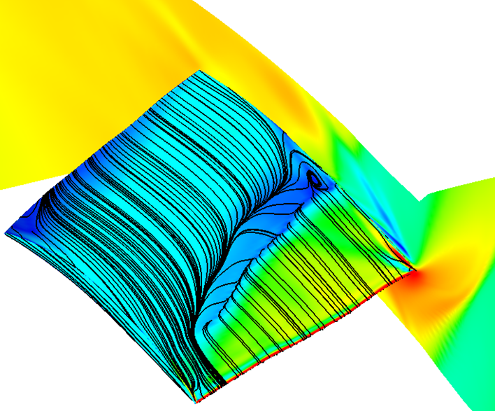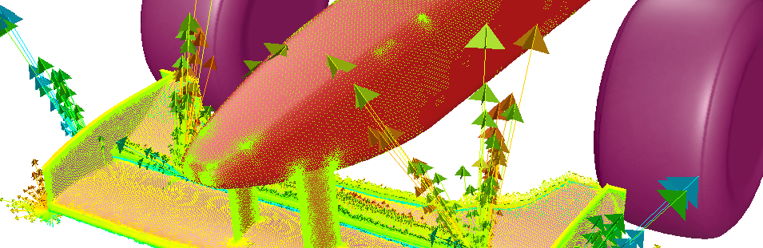
Engineers are continually under pressure to improve the performance of their products and often look to gain an edge using optimisation techniques - trying to reduce drag, increase lift (or downforce), or reduce pressure drop. Rather than relying on intuition to make geometry changes that are often constrained (using a parametric CAD approach), you can now use the new Adjoint solver to compute localised sensitivity data (related to your objectives) and optimize your design semi-automatically.
Archives
Tips on modelling non-Newtonian fluid viscosity

Many fluids we encounter in industry do not strain linearly with respect to viscous shear and are thus considered non-Newtonian. This post explores how to model non-Newtonian viscosity of fluids in ANSYS CFD, using blood as an example.
How to Shrink Wrap a biomedical STL file in Fluent Meshing
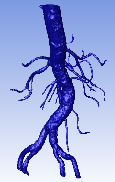
A How-To guide for Fluent Meshing's new Shrink Wrap tool which provides a powerful, easy-to-use solution for meshing complex STL geometries. This is a step-by-step guide on how to produce a high-quality CFD mesh for an abdominal aorta, imported in medium-resolution STL format (NIH).
Using CFD to predict flow-generated noise and other aeroacoustic effects
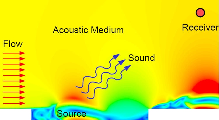
Flow-generated noise can have significantly adverse effects on our everyday lives. Product designers and engineers at the world’s most innovative and successful companies have recognised this fact, and are increasingly using CFD to incorporate noise mitigation strategies into their product design process.
How can I drive Fluent UDF Parameters directly from ANSYS Workbench?

Our support team is tasked with helping our customers to extract maximum value from their CFD simulations, and we are always striving to help customers who work at the bleeding edge of CFD. A common question is: How can I drive Fluent UDF parameters directly from ANSYS Workbench? The ANSYS Fluent User Defined Function (UDF) framework gives Fluent users an almost unlimited ability to modify the physics solved in their simulation model. Customisation can extend from simple properties such as boundary condition profiles, through to complex particle-fluid interaction laws. The ANSYS Workbench interface provides the infrastructure to specify parameters that can be used to drive any simulation inputs (such as geometric dimensions or boundary condition values). By coupling the functionality of Workbench Parameters with Fluent...
Tips & Tricks: Calculating the Mean Age of Air for HVAC simulations in ANSYS CFD
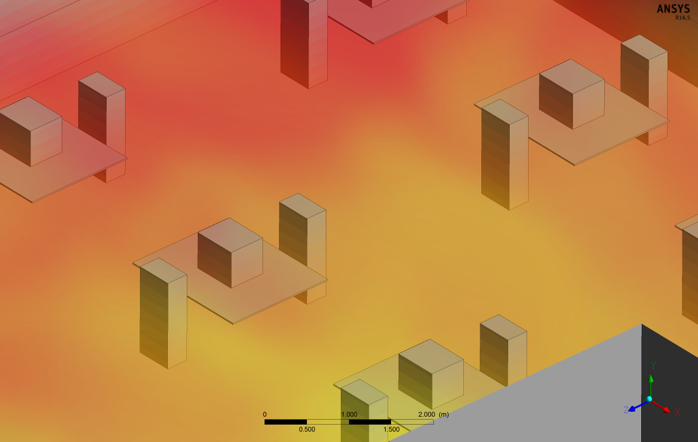
Engineers who are tasked with designing heating, ventilation and air-conditioning (HVAC) systems for buildings will need to assess the indoor air quality to ensure optimum health and comfort for occupants and meet minimum regulatory requirements. Generally a HVAC CFD analysis will take into account variables such as air temperature, relative humidity, air species concentrations and velocity. Additionally, CFD engineers can use ANSYS CFD to solve for the local "mean age of air" (MAA) to assess the air quality within an indoor environment. By examining MAA across the habitable space within a building, engineers can quantify the air change effectiveness (ACE) of their ventilation system and confirm that their design meets NABERS/GreenStar regulations. How can I plot the Mean Age of Air in ANSYS CFD-Post? Usually designers are interested...
Turbulence Part 5 - Overview of Scale-Resolving Simulations (SRS)

An increasing number of industrial CFD users are recognising the need to move away from RANS modelling and resolve a greater spectrum of turbulence (particularly in cases involving large-scale separation, strongly swirling flows, acoustics, etc.). Here we present an overview of Scale Resolving Simulation techniques and important considerations when considering applying SRS to your project.
Tips & Tricks: Estimating the First Cell Height for correct Y+
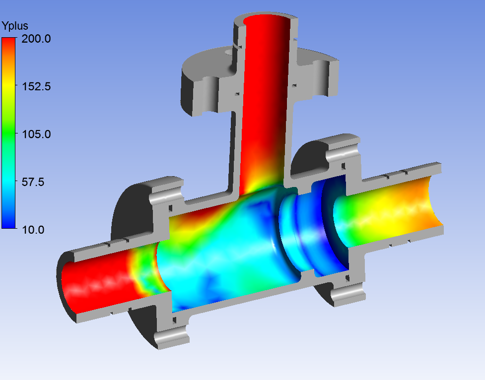
Turbulence Part 4 - Reviewing how well you have resolved the Boundary Layer
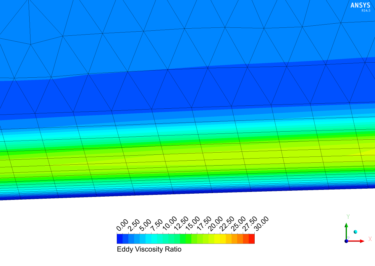
In recent posts we have comprehensively discussed inflation meshing requirements for resolving or modeling wall-bounded flow effects due to the turbulent boundary layer. We have identified the y-plus value as the critical parameter for inflation meshing requirements, since it allows us to determine whether our first cell resides within the laminar sub-layer, or the logarithmic region. We can then select the most suitable turbulence model based on this value. Whilst this theoretical knowledge is important regarding composite regions of the turbulent boundary layer and how it relates to y-plus values, it is also useful to conduct a final check during post-processing to ensure we have an adequate number of prism layers to fully capture the turbulent boundary layer profile, based on the turbulence model used (or...
Turbulence Part 3 - Selection of wall functions and Y+ to best capture the Turbulent Boundary Layer