
In our recent posts on turbulence, we have approached the topic from an industrial perspective where most turbulence modelling is still conducted using RANS models (typically two-equation models which make use of the Boussinessq hypothesis, i.e. the turbulent viscosity). While RANS models are indeed the workhorse for industrial CFD simulations, in an increasing number of cases companies and researchers are recognising the need to resolve a greater spectrum of turbulence (e.g. large-scale separation, strongly swirling flows, acoustics, etc.). In these cases, the information provided by RANS or unsteady RANS (URANS) is limited and we need to consider scale resolving simulation (SRS) techniques.

Difference in isosurface of Q-criterion between RANS (left) and SRS (right) of crossflow over a cylinder
While rarely used a decade ago outside of academic research, SRS is now increasingly being embraced for many industrial CFD applications across Australia and New Zealand. This trend is driven by a combination of continued hardware improvements, improved parallel scalability of modern ANSYS CFD solvers and a number of new turbulence modelling strategies which have made SRS more practical to implement on complex industrial geometries. The main drawback of SRS has been that it requires a suitably fine meshing resolution as well as suitably small timestep in order to obtain accurate results (within a practical timeframe). In the past, these two factors had combined to push SRS out of reach for most industrial CFD users (beyond the lucky few who had access to supercomputing hardware!).
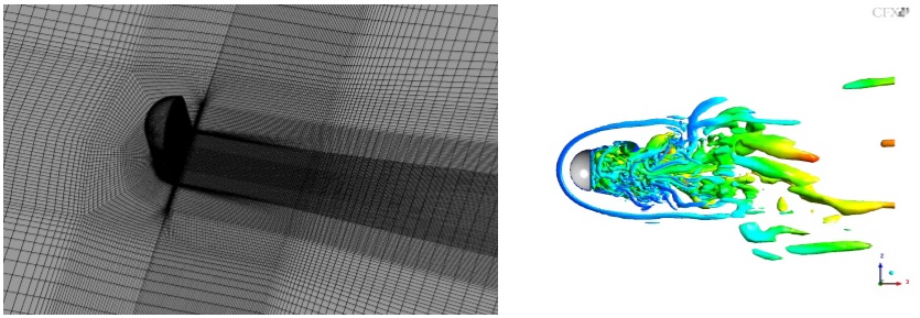
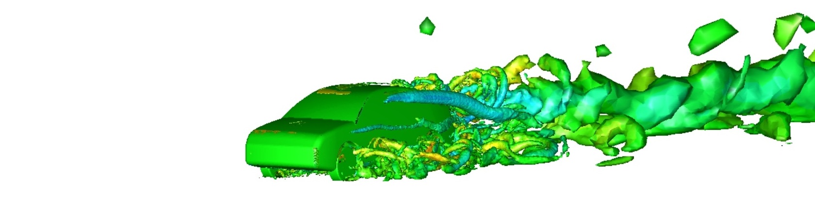
Mesh resolution for a scale-resolved simulation (SRS) of flow over a car mirror
When faced with the necessary compromises, industrial CFD users had typically chosen a URANS approach which provides a nonphysical single-mode transient behaviour that is dominated by the turbulent or RANS length scale. In contrast, a SRS strategy aims to resolve all (or a portion) of the turbulent spectrum and considers all turbulent length scales to the grid or dissipative limit. In ANSYS CFD, the most detailed approach that is available is Large-Eddy Simulation (LES). A LES approach essentially resolves all large turbulent structures (which have the bulk influence on the flow-field) up to the available grid limit and dissipates the energy from Kolgomorov scales via the introduction of a sub-grid scale model. The use of LES in a practical timeframe is not feasible for wall-bounded flows at high Reynolds numbers, due to the requirement for excessive grid spacing in the boundary layer when using LES. For this reason, LES has previously been regarded as most applicable to free shear flows. However, recent development of a Wall-Modelled LES (WMLES) approach has meant that less stringent meshing (and, consequently, temporal resolution) requirements can be used in the boundary layer which means that WMLES is applicable to a wider range of industrial problems.
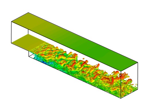
Large eddy simulation (LES) of the flow over a backward-facing step to capture separated profile
To rectify this issue relating to suitable grid resolution in the boundary layer, ANSYS CFD has also developed a number of hybrid SRS models which limit the resolution of turbulent structures to all regions which fall outside the boundary layer. This strategy is optimal for wall-bounded applications, since RANS models are utilized locally to resolve the boundary layer whilst the turbulent scales are properly resolved in the unsteady regions.
The choice of most suitable SRS modelling strategy will depend upon your application.
- Detached-Eddy Simulation (DES)
Detached-Eddy Simulation (DES) is the classical hybrid model which applies a discernable interface between RANS and LES regions. The idea is to avoid the high resolution requirements of LES in the boundary layer, which is often stable, and apply LES to the separated or 'detached' regions of the flow. This method however carries the same grid sensitivity requirements as pure LES in the detached regions, and past experience has proven that results are highly sensitive to grid spacing which precludes DES from being used with confidence on arbitrarily complex industrial geometries. Fortunately, users benefit from the recent introduction of Delayed DES (DDES) which is a direct extension of the DES model which provides additional shielding functions to ensure that the model does not inadvertently switch to LES within the boundary layer as a result of grid sensitivity. As such, DDES is now the strongly recommended alternative to DES.
Triangular cylinder in crossflow showing isosurfaces of Q-criterion calculated via D-DDES. The inherent instability in the wake makes it a perfect candidate for a hybrid RANS-LES technique.
- Scale-Adaptive Simulation (SAS)
Of all the SRS models available within ANSYS CFD, the safest approach for inexperienced users is to use Scale-Adaptive Simulation (SAS). SAS is an extension of the SST (URANS) model which is much less sensitive to the grid (compared to DES) and is becoming widely accepted as the industry standard for unsteady turbulent flows. The SAS model includes additional terms in the RANS equations to provide LES-like behaviour in any separated and detached regions of flow. In all regions where there is insufficient flow instability or spatial/temporal resolution, the SAS model will automatically fall back to a URANS approach, making this a robust approach for the majority of transient industrial applications.
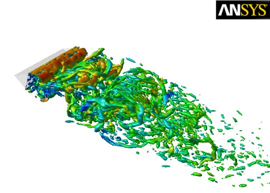
Scale-adaptive simulation (SAS) of a turbulent jet in cross-flow showing iso-surfaces of Q-criterion
Both of these hybrid models (DDES and SAS) implement a RANS approach within the boundary layer, so the normal RANS meshing requirements apply and should be followed as strictly as possible. Within the boundary layer, in general the user should aim for Y+ = 1. However, in certain cases where we expect geometry-induced separation, good results can still be obtained using a suitable number of inflation layers (10-15) within the boundary layer and a Y+ resolution that is suitable for wall functions (ie. with y+ residing in the log layer, see our previous posts). When using this simplified approach, we need to ensure that in regions where we’re expecting unsteady ‘LES-like’ behaviour that our grid is sufficiently fine to resolve these transient turbulent structures, and also that our timestep is such that Courant number is close to 1. The use of a bounded central differencing scheme for spatial discretization is also strongly recommended.
In even more recent developments: Another alternative approach (which again reduces the computational requirements of LES) is the use of an embedded-LES (ELES) region within your RANS domain. This approach is perfect for cases where the flow instability is not strong (which may cause problems with DDES and SAS), or strongly localized within the domain (in which case it makes sense to only apply the onerous LES mesh requirements in this local region!). At the RANS-LES interface, turbulent synthesisation methods are applied to generate turbulent instability. This approach is utilised where we have a strong localized region of instability, or in cases where the flow is very stable and requires synthetic turbulence to be generated in order to capture the physical turbulent spectrum.
In general, our experience has shown that you can expect to achieve consistent results using both of these “hybrid” SRS methods, provided you are using appropriate spatial and temporal resolution, and your flowfield has sufficiently strong flow instability to generate LES behaviour in the detached-flow regions.
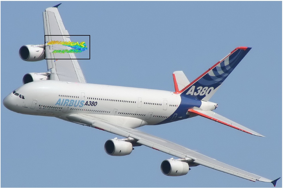
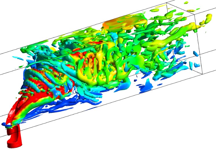
Example of the use of embedded-LES. The entire aircraft may be simulated using RANS but identified areas requiring higher-fidelity or detailed information on the turbulence spectrum (ie. surrounding the engine nacelle) can be resolved using LES. Image courtesy Airbus Gmbh and ANSYS Inc
One additional comment: Once we have decided on the most appropriate SRS modelling and meshing approach, we need to consider how we intend to capture and present our results. Typically we would intend to report statistically-averaged results which are representative of the transient flow in the domain, in which case we should run the simulation for sufficient time so that the flow has traversed the domain a number of times.
We hope that this post has provided a good introductory overview of the Scale Resolving Simulation approaches available in ANSYS CFD. The invention of new hybrid (DDES and SAS) and embedded (ELES) methods has opened the door to accurately capture LES-like flow behaviour for many industrial applications. However, as with any numerical modelling techniques, they should be used with good judgement and care. By following the above guidelines and building upon experience from validated test cases (supplied by ANSYS), the implementation of SRS will provide a high-degree of accuracy for transient turbulent flows at the minimum computational cost. However, poor implementation of these models will only result in rubbish that has still taken days to compute!
Please post a question in the comments below or send us an email for further advice in this area.


