
The water industry has a range of engineering challenges and specific regulatory requirements, especially concerning flow assurance, water quality, and even component selection. Last week, I was visiting a client in NSW and, as we got talking about their requirements, it became clear that CFD was a tool that would deliver real value to their business – the ability of the numerical modeling to predict complex flow behavior, across individual components or large network systems, makes it a perfect analytical tool for the water industry.
So for the unfamiliar: What is CFD and Why Bother?
Computational Fluid Dynamics (CFD) is a type of numerical modeling, whereby engineers and designers can use a virtual simulation approach to assess the performance of their product or process – non intrusively – before even building a prototype. Be it in the early FEED stage, detailed design phase or troubleshooting in post production to "understand what is going on", CFD is increasingly being used in water, medical, oil and gas and the renewables industries. Actual products that are out in the real world, saving lives and generating electricity – have all started as a virtual model in CFD simulation.
One core benefit of CFD is its accessibility and ability to give results with a quick turn-around time frame. In today’s commercial world, getting the ‘right answer’ or design is of no use, if the tool that delivers it is not easily understandable or accessible to more than just a handful of people within the organisation. Moreover, in a world of faster computers and smart phones, engineers are also looking for a tool that deliver results and point to a sensible design within hours, rather than weeks or months.
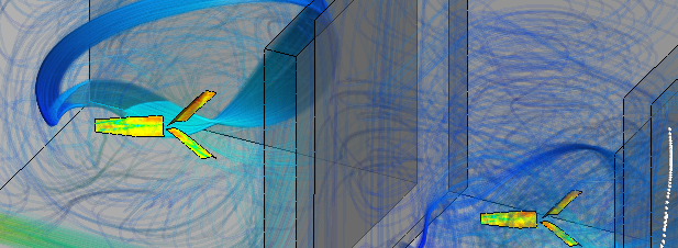
Take for example, a system of typical complexity at a wastewater treatment plant, as shown below in Figure 1. Besides showing the obvious fluid path, CFD also shows regions of recirculation, high velocity areas, effectiveness of the rotating impellers for mixing, air bubbles being injected for aeration, bubble trajectories and forces acting on the impellers due to fluid momentum and torque – all this from a single static snapshot, obtained from a CFD simulation.
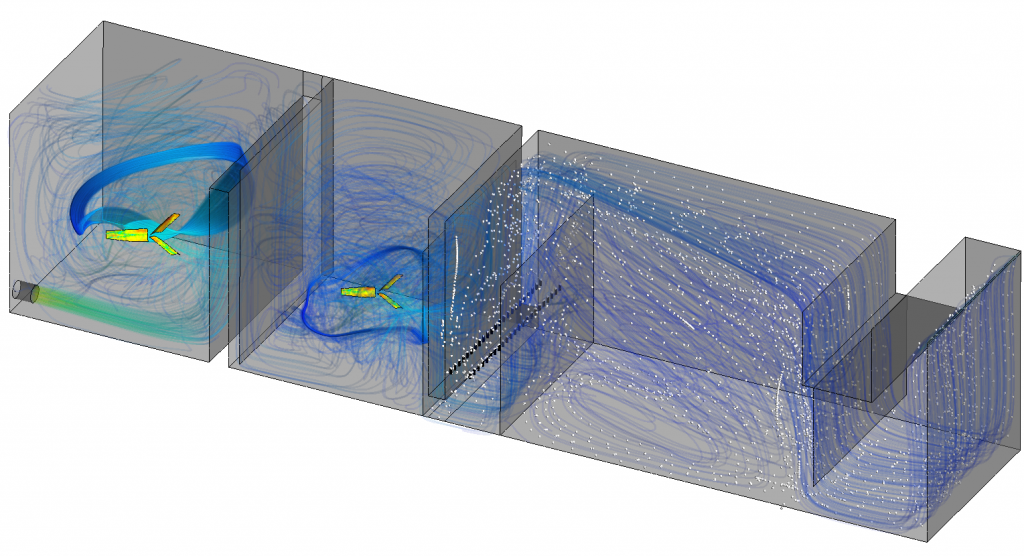
Figure 1
‘Do We Need A Team of Phd’s?’’
That is probably the most common question I get asked when I am speaking to a client and the answer to the question is: no, you don’t. One of the major returns on investment with CFD is the fact that anyone can do it, once the initial model has been setup by a suitably qualified person.
How do we make this happen?
ANSYS, for example, have taken great pains to ensure easy access to a novice and expert alike. Once a simulation has been solved – and this goes for CFD, structural analysis or coupled physics even, the model can easily be parameterised to run any number of geometric, material or operating condition permutations and combinations. Using Figure 2 as a reference, the operating fluid density, inlet conditions and impeller rotations are variables that have been parameterised. Once the initial run has been completed, any other user can assess N design points by simply filling in the table as shown below. As there is no limit on the number of parameters assessed or simulations run, it is easy to see how CFD can become a powerful tool to assess ‘what-if’ geometric designs and operating conditions on the fly.
Depending on where the user is in the design cycle, CFD can then be used to steer towards or away from a particular route quickly and effectively.
Compare this with a physical prototyping/experimental approach, where a user would always be relying on a select few individuals to setup the experimental rig and run the tests. Also, with each test setup, there are significant costs and tie delays associated with materials, shipping, availability and building of the experimental model.
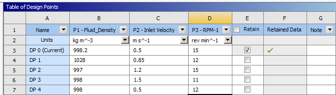
Figure 2
More Than Contour Plots and Animations
At its heart, CFD brings all the benefits of a digital tool. Implicitly this means, the full range of statistical or other mathematical analyses such as sensitivity studies or multi-objective optimization algorithms can be applied to any simulation. This becomes particularly useful in complex systems, where the inter-dependency between variables isn’t clear or known a-priori.
Moreover, because CFD solves the fundamental fluid equations (Navier-Stokes) for any arbitrary component or system, regardless of its shape or complexity, the user is not limited to working with just the standard variables of pressure, velocities, mass flow rates, etc. Using additional variables, more complex or industry specific parameters can easily be setup. If for example, chlorine concentration or UV radiation dose rate is an objective, these variables themselves can be setup as custom parameters that are tracked and reported throughout the simulation domain.
From Local Components to Entire Grids
Typically, when new users think of CFD, the image of a streamline on a 3D CAD comes to mind. This isn’t always true as CFD can also model 1D systems, as shown in Figure 3. The example shown has been built in Flownex (a systems level CFD tool) showing a small part of the water network grid of a city, complete with pipe work and ancillary equipment, such as valves, pumps, etc.
Besides providing flow assurance and quality analysis, the model can capture water hammer, PID behavior, flow balancing, valve opening/closure times and can also be used as a first start to sizing pumps and pipework that will deliver a certain flow rate and pressure. Additionally, a typical Flownex 1D simulation will solve in seconds or minutes, compared to minutes or hours for 3D CFD simulations.
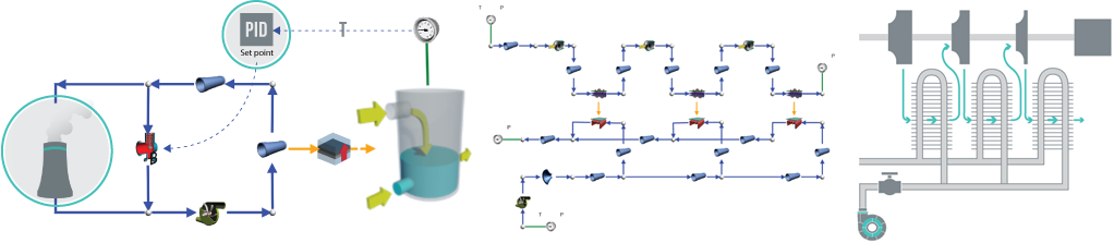
Figure 3
Using this top-down network approach, the overall system can first be assessed to check if an idea will work in principle first, and identify what gross parameters are required to achieve the net objective. Building from there, a system-level model can be coupled with a 3D component-level model to design or size a specific part of the flow path as required.


