In the past few decades, as rocketry and the going-to-space endeavour become more and more commonplace, knowledge and expertise have gradually shifted from a solely public enterprise in the hands of a select few government bureaucracies to private firms and academia. In the world of academia, this paradigm shift and increased accessibility have stimulated various student teams and research groups to come together to design, simulate, build and launch their own rockets. Over the years, a few efforts have seen successful space launches, including the civilian rocket CSXT, or more recently the university team USCRPL’s Traveller IV using a student-designed and manufactured solid propellant.
Following in their footsteps, there is an active effort by students from the Australian National University’s (ANU) Rocketry team to develop a rocket capable of passing the boundary of outer space and being safely recovered by parachute upon re-entry. Founded in 2018 to participate in the Australian Universities Rocket Competition (AURC), members of ANU Rocketry have only launched commercially available solid-fuel propelled rockets.
Solid rocket motors are commonly used at the amateur and intervarsity levels due to their relative ease of handling, storage and reduced complexity. Despite these advantages, the largest commercially available solid motor, the O8000, still falls far short of the minimum required impulse for a rocket vehicle to reach space. It is for this reason, among many others that the team at ANU Rocketry have taken on the challenge of developing our in-house designed and 3D manufactured bipropellant liquid-fuel engine, using liquid oxygen (LOX) and bioethanol for our Space Rocket Project.
This blog post shall give a snapshot of ANU Rocketry’s aerothermal analysis to predict the heat flux at the space rocket’s leading edges during its hypersonic ascent phase. The aerothermal analysis is directed by three primary goals:
- Investigate key flow behaviours around the nose cone of the rocket.
- Determine the maximum heat flux the vehicle may encounter through an aerothermal analysis. This shall be done through a two-pronged approach: first using engineering methods to derive aerothermal loads based on experimental data and simplified formulas, then conducting Computational Fluid Dynamic (CFD) simulations to further validate the engineering predictions.
- Use the aerodynamic heating outputs to inform vehicle design considerations.
As a starting point, the vehicle’s trajectory and key atmospheric parameters at the altitude of interest are fed into analytical models. Of note is the seminal stagnation point heat transfer formula developed by Fay & Riddell formula developed in the late 1950s, which has been extensively validated through empirical wind-tunnel data. The model predicts the stagnation point heat flux at the nosecone tip of the rocket to be ~550kWm^(-2).
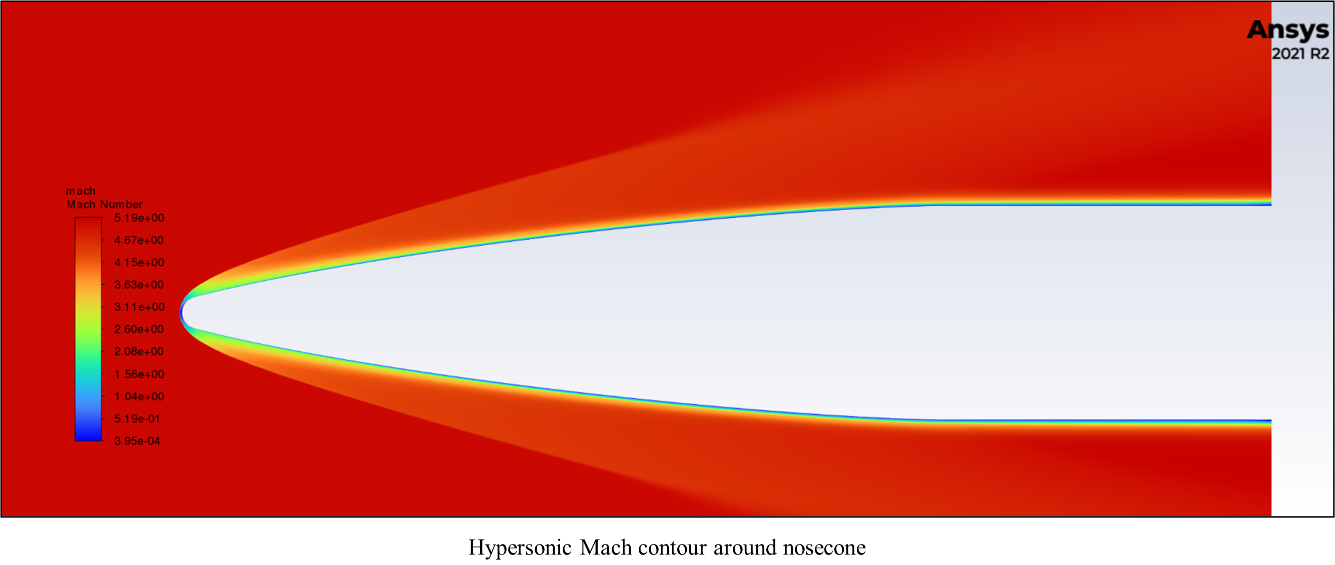
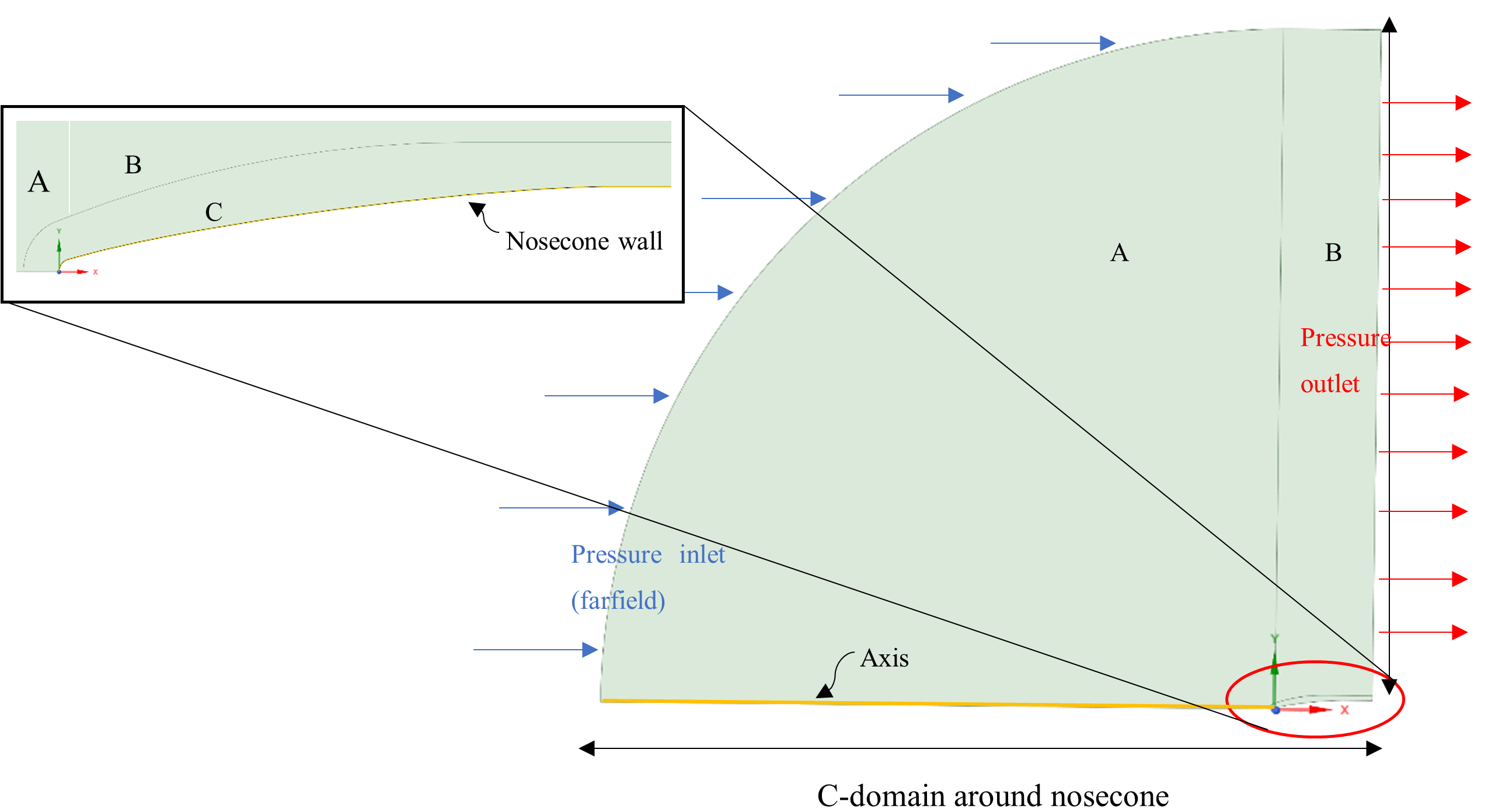
Ansys CFD is then used as a means to validate the analytical prediction. Given the symmetry of the nosecone geometry, a 2D axisymmetric approach is chosen to reduce computational requirements while still maintaining simulation fidelity. The boundary conditions and flow domain around the geometry of interest is shown below:
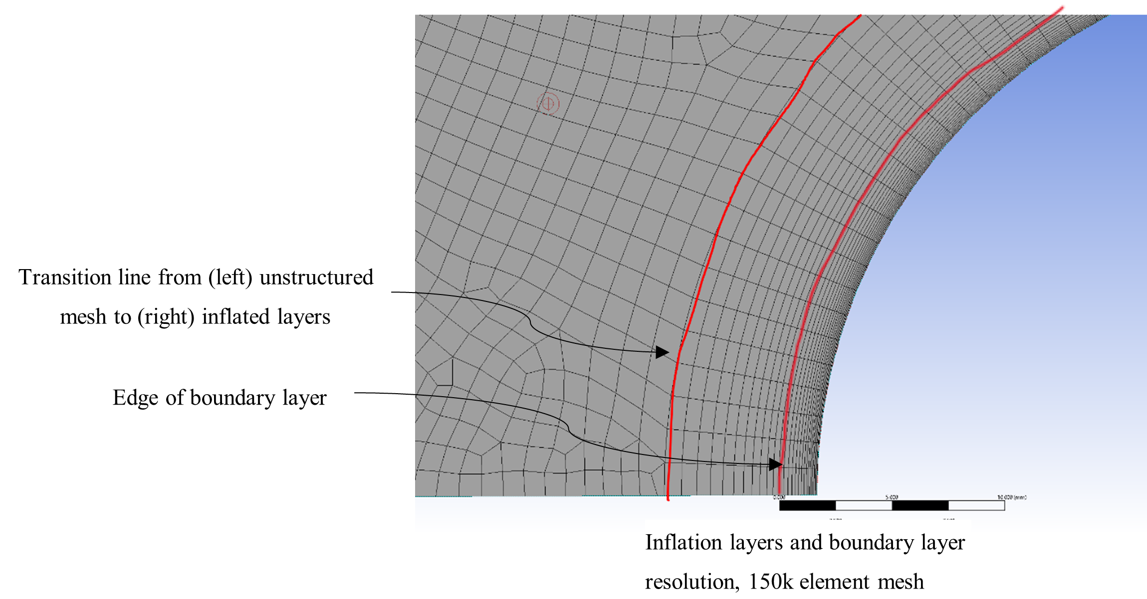
The meshing scheme is carefully selected, and is a balancing act between precious computational resources and simulation fidelity. Elements close to the nosecone wall must have sufficient mesh resolution to capture the sharp thermal and velocity gradients. A sample rough mesh is shown below, of around 157k elements showing various regions of different mesh sizes.
The following solver settings were used for the simulations:
| Solver | Density-Based |
| Formulation | Implicit |
| RANS Model | 𝑘−𝜔 SST |
| Discretisation scheme | Least Squares cell-based, second order upwind |
| Convergence acceleration | Convergence acceleration for stretched meshes (CASM) |
| Initialisation controls | FMG initialisation |
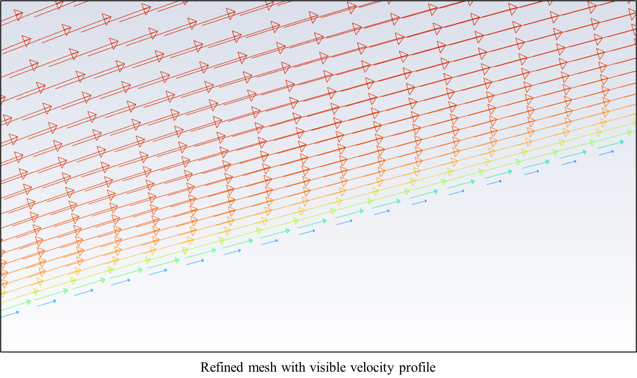
5 sets of simulations are conducted as part of a mesh independence study to verify the CFD analysis. Mesh elements are increased sequentially, beginning with a coarse mesh of around 150k elements. After each set of simulation, the mesh is refined to more accurately capture the thermal and velocity gradients. Figure below shows a refined mesh with a clearly visible velocity profile.
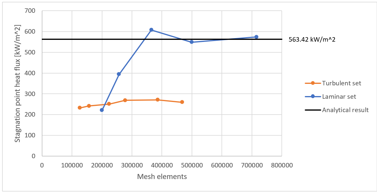
After 5 iterations, the solution stabilises on a final mesh of up to 700k elements for the laminar set. With this final solution from the mesh independence study, the CFD analysis verifies the analytical results of 563.42 kWm^(-2) to within 5%.
The Ansys CFD analysis has provided a critical tool for the team at ANU Rocketry to refine the design of our vehicles, providing an accurate means to validate our analytical calculations. Moving forward, the team will use the simulation outputs to inform design choices for the nosecone tip at the stagnation point of interest. This includes further refining the geometry of the tip as well as material selection to withstand the high temperature and heat flux expected. Further, the simulations will extend downstream to investigate the flow at the fin leading edges and assess the aerothermal considerations there.
We would like to thank the team at LEAP Australia and Ansys for their sponsorship and continued mentoring & support as our team endeavours to reach new heights.