USYD Rocketry Team (URT) is a highly technical student led team from the University of Sydney. The Team strives for excellence in the development of high-power sounding rockets through systems engineering, experiential learning, and a focus on safety. URT has been a competitor in the Australian Universities Rocketry Competition (AURC) and Spaceport America Cup since 2019, being the first Australian team to compete and take first place in the 10,000 ft COTS category with the Silvereye rocket.
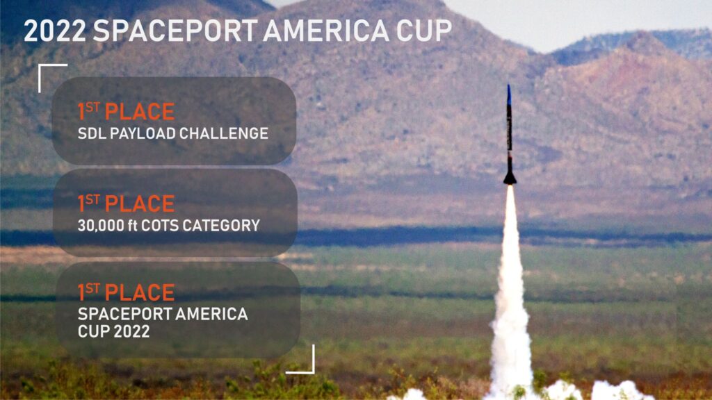
Update June 2022: Since this post was written, USYD Rocketry Team took out first place in the 30,000 ft COTS category at Spaceport America Cup 2022 with their rocket, Bluewren, and first place in the Space Dynamics Laboratory Challenge 2022 with their target localization for space junk capture demonstration, Callistemon. In addition to this, the Team won the Spaceport America Cup, the most prestigious award for rocketry in the world.
Our team’s relationship with LEAP Australia began in 2019 after the success of Silvereye, as we recognise that professional consultation for the ANSYS simulation suite can improve the design and analysis of future rockets. This relationship helped us to achieve first place in the 30,000 ft COTS category, and second place in both the 10,000 ft COTS category and the SHOAL Award for Modelling & Simulation at AURC 2020.
Update June 2022: For the 2022 campaign, our team used resources provided by LEAP Australia in our modelling of Bluewren, which was used in our in-house developed high-fidelity trajectory simulation software. Bluewren’s final apogee at Spaceport America Cup 2022 was 29,933 ft, a mere 67 ft from the predicted apogee of 30,000 ft!
The remainder of this post was written in 2021 prior to the development of our current software and outlines previous methods used for trajectory analysis.
Trajectory Simulation
The target of a rocketry competition is to design and construct a rocket capable of reaching a certain altitude (or apogee). The three variables that will determine the apogee are the airframe geometry, the motor thrust, and the total weight of the rocket. While the latter variables can be tuned independently of flight conditions, the airframe geometry must be modelled accurately for prediction of the aerodynamic forces and moments that will significantly influence the apogee.
Our previous method of modelling the rocket and determining the apogee used established open-source trajectory simulation software: OpenRocket. This is a suitable software package for subsonic aerodynamics, however simulations using this software for transonic and supersonic regimes are less accurate. Part of the Team's success can be attributed to our focus on innovation, and our solution to these limitations has been to augment the OpenRocket software. This can be achieved with a database of non-dimensional aerodynamic derivatives derived from Computational Fluid Dynamics (CFD) simulations to accurately determine the forces and moments on the desired rocket for different flight conditions.
In order to reduce the number of required simulations, the task of three-dimensional CFD of the Silvereye rocket was simplified using the following considerations:
- Angle of attack and sideslip angle may be deemed approximately equivalent for the cylindrically symmetric rocket. Therefore, the pitch and yaw axis forces and moments are equivalent. This will halve the required simulations, as the effects sideslip angle do not need to be modelled.
- Only aerodynamic derivatives according to static variables were considered (e.g. drag coefficient with respect to angle of attack, not with respect to the rate of change of angle of attack). This will ensure rapid convergence using the steady-state solver.
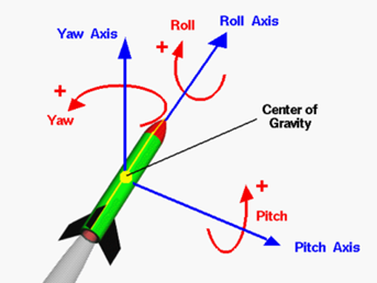
Figure 1: Rocket Body Axes (https://www.grc.nasa.gov/www/k-12/rocket/rotations.html)
This article describes the workflow for the CFD simulations performed for our subsonic Silvereye rocket to validate this new method against flight test data, in preparation for implementation with our supersonic 30,000 ft Firetail rocket.
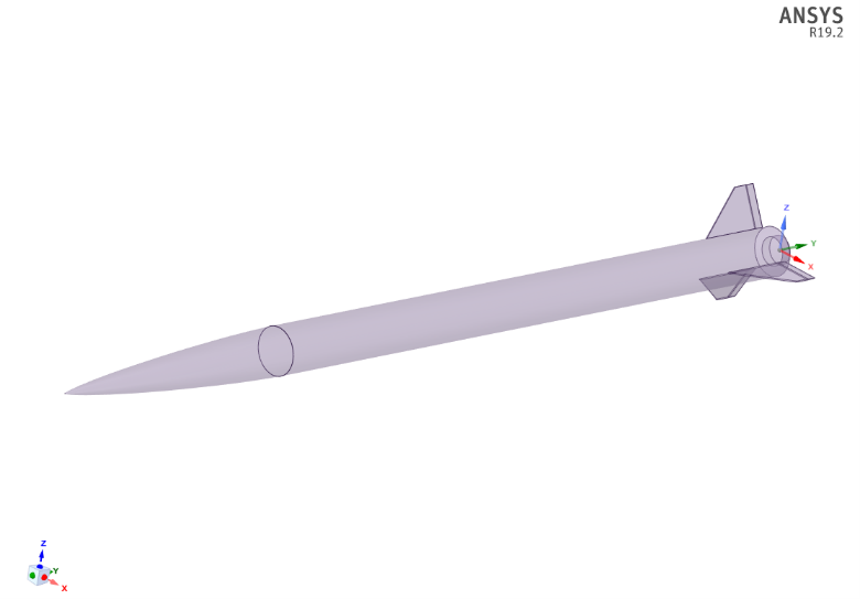
Geometry Modelling in Spaceclaim
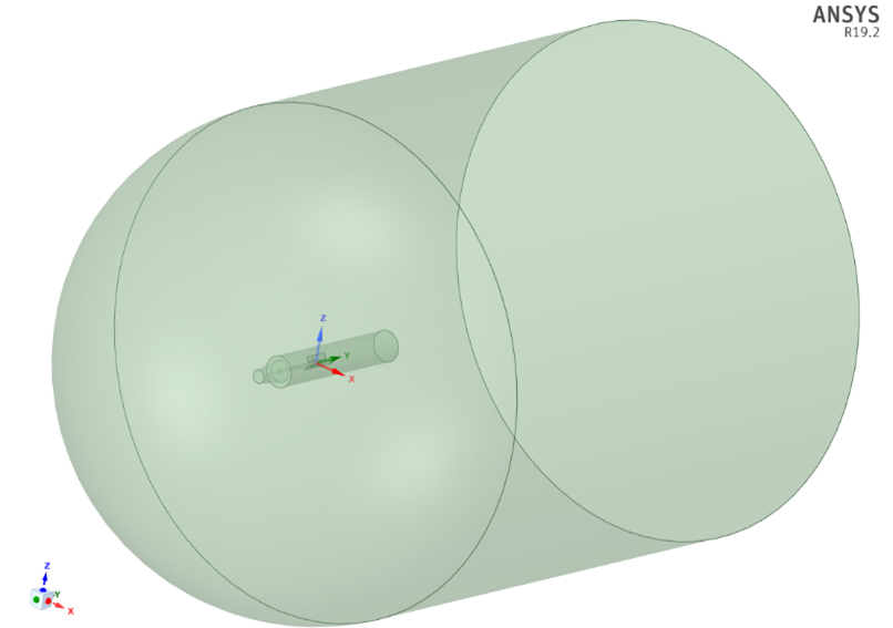
The rocket geometry was modelled and simplified in ANSYS Spaceclaim after importing from Solidworks. The original geometry contained protuberances and holes that would provide negligible higher order flow field effects; therefore, they were removed. The geometry was repaired using the merge faces and split/extra edges functions. The simplified rocket was then wrapped in a hemispherical inlet, and cylindrical pressure outlet extending downstream to match the rocket’s cylindrical symmetry. The flow domain was set with an outer diameter of 20 m, compared to the rocket diameter of 15.7 cm, and a length of 3 m, to sufficiently ensure far field conditions are satisfied. Bodies of influence were placed around the nose cone, body tube, and fins to resolve the flow field around the surface of the rocket and its wake. For the initial geometry modelling, LEAP’s consultation was of considerable help, as was their Rocket Competition Simulation YouTube playlist.
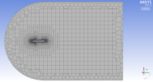
Fluent Meshing
Fluent Meshing was chosen to allow faster automated meshing workflows for future rockets, compared to ANSYS Meshing. The use of unstructured poly-hexcore meshes compared to structured quadrilateral meshes was justified by maintaining solution accuracy using an iterative procedure of meshing the rocket for a target y-plus value of one or below to resolve the viscous sublayer of the boundary layer. This would accurately model the wall shear forces in the boundary layer and, therefore, the most important aerodynamic parameter: the drag force on the rocket. This procedure was built upon one of LEAP’s previous blog posts. The procedure was performed for the maximum Mach number in the rocket’s estimated flight profile of 0.77. The boundary layer thickness decreases for higher airspeeds, therefore the density of the mesh inflation layer for Mach 0.77 should accurately resolve the boundary layer for lower airspeeds. The resultant first inflation layer height was determined to be 0.005 mm, and the final minimum orthogonal quality was 0.03 after using the Improve Volume Mesh function.
ANSYS Fluent Solution
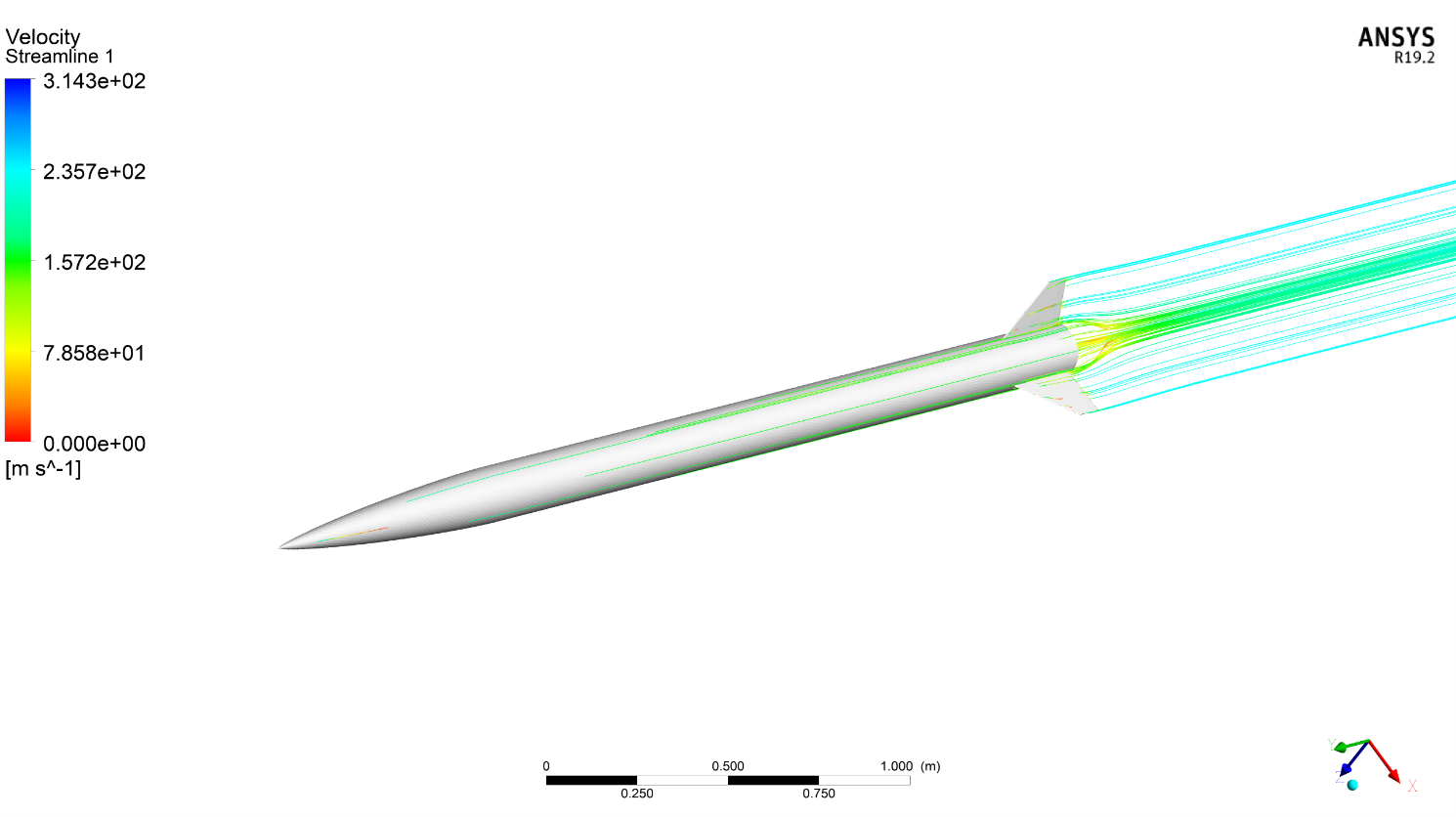
After importing the mesh file into ANSYS Fluent, the steady-state solver was chosen, as only static aerodynamic parameters are to be calculated. The k-omega SST turbulence model was chosen for its well-established industrial level accuracy and compromise between resolution of the boundary layer and freestream flow field. Ideal gas and far-field boundary conditions were chosen, as there will be significant compressible effects as the rocket accelerates past Mach 0.3.
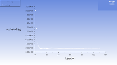
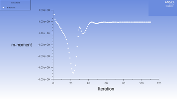
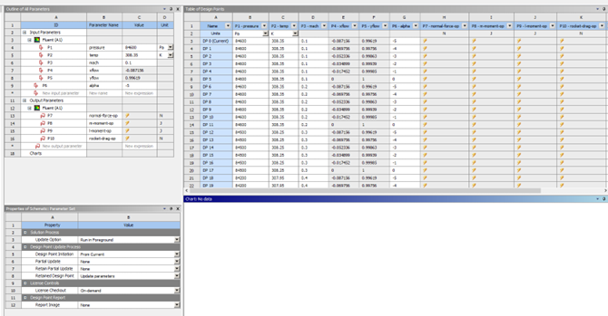
To automatically solve for different conditions in the rocket flight profile, workbench parametrisation was used. The x and y axis inlet velocity unit vectors were parametrised to control the incident angle of attack, while the Mach number, ambient pressure and temperature were parametrised to set the flight conditions at different phases in the estimated flight profile. The roll axis force, pitch/yaw axis force, pitch/yaw moment, and roll moment were set as output parameters to monitor variable convergence. Finally, the problem can be solved using the coupled pressure-velocity coupling method for the fastest single-phase implementation, using the pseudo-transient solver with higher order relaxation. The problem was initialised using the hybrid option, and then solved over 150 iterations. In total, 77 design points for different Mach numbers, angles of attack and their related flight conditions were simulated within a month from workbench.
Results and Analysis
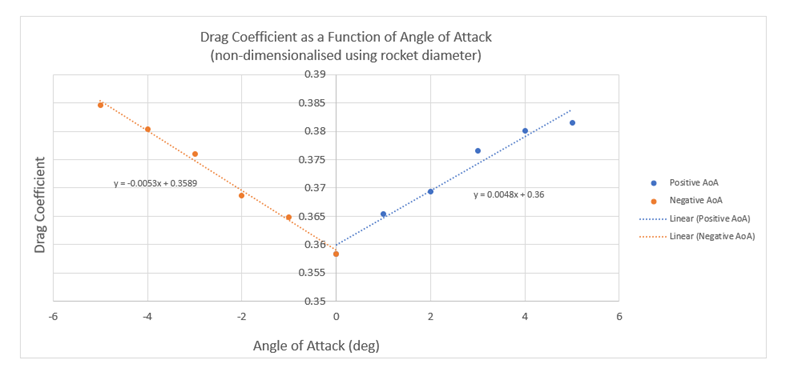
The resulting output aerodynamic forces and moments were non-dimensionalised using the rocket diameter and flight conditions. The first order derivatives, with respect to angle of attack for a specific Mach number, were then discretely approximated using linear regression. These derivatives will be used to accurately model the three-dimensional Silvereye flight trajectory, which will be compared to recorded flight test data to validate the modified OpenRocket software. The Team is looking forward to optimising this method of deriving the aerodynamic coefficients from CFD using the workflows established in this project for use on our future rockets. Additionally, we will explore implementation of the adjoint solver as a replacement or supplement to this method.
The Team would like to thank LEAP Australia for all the help and expertise offered to us through 2020 as we look forward to an even more productive 2021 and future campaigns!