
Simulation of manufacturing processes for polymer components combines elements of the most challenging non-linear finite element problems with additional thermal, viscous and material flow considerations. These processes exist in the middle ground between Lagrangian based structural finite element simulations in which the mesh and nodes defining the bodies move and deform with the material, and Eulerian based CFD simulations in which the mesh is static and the material moves through the mesh. In the former approach the level of material deformation is limited by the ability of finite elements to deform while retaining numerically accuracy, and in the latter CFD approach the detail of the outer surface of the material is not captured as accurately and it is more difficult to maintain local thermal and strain histories for the material.
ANSYS Polyflow has been purpose built for this domain of simulations by using a combination of the Lagrangian finite element approach and frequent re-meshing thus allowing fluid-like behaviour and temperature dependent Newtonian and non-Newtonian material characteristics to be captured.
While Polyflow is primarily focused on simulating blow moulding and extrusion processes, it is also used for mixing of complex rheology liquids, film casting, extruder screw simulation, gravity assisted gob forming, glass pressing and mould filling. The results of these simulations can also be coupled to other analysis systems within ANSYS Workbench to analyse the post-forming mechanical behaviour of the park. For example, the thickness distribution calculated in a glass bottle blow moulding simulation can be mapped on to the mesh in a drop test analysis to determine how the thickness distribution affects the impact survivability.
Extrusion and inverse extrusion analyses
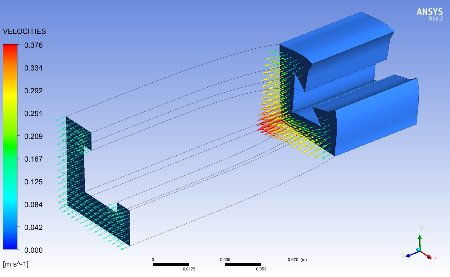
Extrusion simulations are used to predict the shape of the extruded product from a given die shape and process conditions. The cross-sectional profile of the extruded product will not match the die shape exactly because the extrudate fluid viscosity and no-slip boundary conditions on the die wall result in non-uniform fluid velocity field at the die outlet, with higher velocities occurring in thicker regions and lower velocities in the thinner regions. As the fluid exits the die the velocity profile equilibrates and the profile changes shape in order to accommodate conservation of volume. This effect can be seen in the image below in the extrusion prediction of the quarter-symmetric cross-section extruded shape.

The inverse extrusion simulation works backwards from this state to determine what the shape of the die should be in order to achieve the desired extrudate cross-section profile. Thin sections of the die will tend to be thickened in order to increase the fluid velocity and thick sections will become thinner to reduce the velocity. The die shape predicted by the inverse extrusion simulation is shown below.
In summary, companies working with extrustion dies are typically able to use ANSYS Polyflow to:
- Easily review multiple design options using What if” strategies
- Design dies faster
- Understand and eliminate flow related problems
- Significantly reduce overall costs for engineering of extrusion lines, die fabrication, and reducing scrap material
- One company using Polyflow for die design found it delivered a 200 percent ROI the first year alone!
Thermo-forming
Thermo-forming involves using either air pressure or a rigid tool to force a pre-heated blank or parison to conform to a mould. In this example the forming of a plastic car bumper has been modelled by preheating the blank then forming it between a matched punch and die pair in a manner similar to sheet metal stamp forming. Thermal conduction between the blank and tools causes it to cool as it forms and local membrane straining results in changes in the material thickness. The large elements that the blank is initially meshed with are not capable of capturing the small curvature regions of the die surface so adaptive meshing is used to subdivide the elements based on proximity to the die and the local curvature.
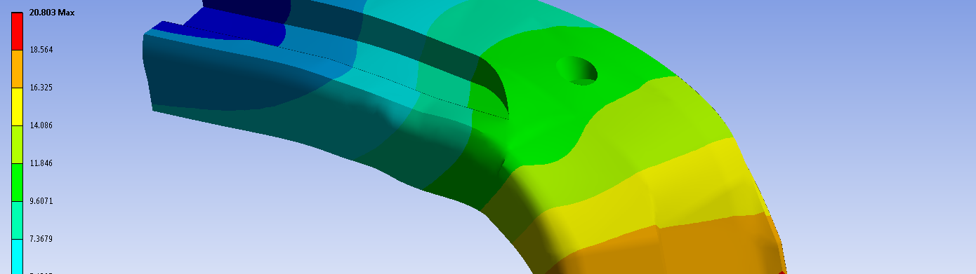
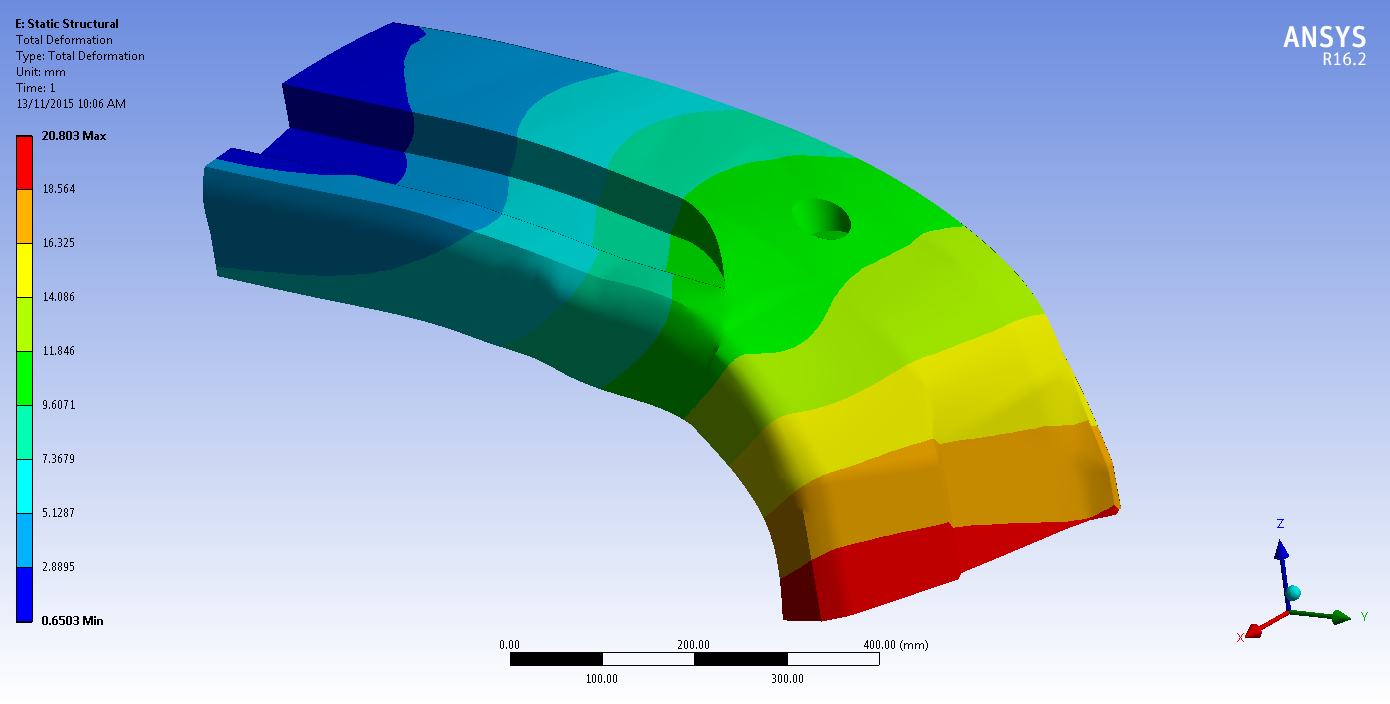
The thickness and temperature results can be directly coupled to other analyses in ANSYS Workbench to investigate how the forming process will affect the performance of the part. In the Static Structural analysis both results are mapped on to the structural mesh and a static analysis is run to determine how shrinkage due to cooling of the part after removal from the mould will affect the shape and the resulting residual stress distribution.

The thickness distribution was also mapped on to the mesh in an explicit dynamics analysis and the bumper was impacted with a cylindrical body to determine the ability of the design to absorb energy.
Ultimately the deflection, stress, thickness, temperature or other simulation output value can be parameterised so that DesignXplorer can be used to find the optimum forming process conditions to meet design requirements. This is achieved by fitting a response surface to the solution of a set of design points in a design of experiments (DOE) table. Once the response surface is generated an optimum design can be chosen based on specified criteria.
If you would like to learn more about how ANSYS PolyFlow can speed the design and production of extrusion dies, the ANSYS website has a number of resources available including a recorded webinar on Virtual Prototyping in Rubber Seal Manufacturing and Testing.


