
Advancing our understanding of the fluid dynamics within a pump is of prime importance in improving pump efficiency and thus helping engineers to reducing the losses incurred during pump operation. Ansys has a robust end-to-end workflow to help designers in creating pumps from scratch. One example of how such a workflow helps improve pump efficiencies can be found here.
However, clients sometimes need to investigate ways to improve an existing pump’s design without needing to go back to the pump’s designer for their CAD drawings. This blog showcases how Ansys CFD software can help design a custom workflow to meet the client’s need for investigating the flow physics in a pump, starting from a scanned model of the geometry.
Simulation Objective:
In this case, the client had scanned data for an Ingersoll Rand HLV series pump at their disposal and approached LEAP Australia to help set up a CFD simulation to calculate the efficiency of the pump to compare it with experimental data. The CFD team at LEAP Australia devised a custom workflow by cleaning up the geometry in Ansys SpaceClaim, meshing the cleaned geometry in Ansys Fluent Meshing and setting up the simulation in Ansys CFX. The converged CFD simulation is post-processed in CFD-Post to extract key quantities of interest, such as the pump efficiency, the generated head, the power draw by the pump and the torque acting on the blades. The quantities predicted by CFD simulation agreed well with the Client’s experimental data. Finally, Ansys Ensight is used to create high quality animations to visualize and understand the flow of water within the pump.
In this blog, we will provide an overview of the key steps in this analysis and explain how such a workflow can be leveraged by clients to improve existing designs without needing to go back to the original supplier for CAD.
Clean-up in Spaceclaim:
Since the client had a scanned geometry, Ansys SpaceClaim was the go-to tool of choice to prepare the geometry for meshing. Ansys SpaceClaim has an excellent suite of features that can be used to quickly clean up any geometric features that could lead to poor quality elements in the mesh.
SpaceClaim can quickly close gaps between surface bodies, fill missing faces, clean up split edges and delete any extra edges that are surplus to the meshing process. All these tools are conveniently located in the repair tab to help analysts quickly clean up their geometries.
A key challenge of the clean-up process was to ensure the leading edge of the impeller was captured with a feature edge. This feature edge would be used by the meshing tool to adequately capture the leading-edge curvature of the impeller blades. SpaceClaim has a “Split” tool that can split any complex surface at the given location and create a feature edge that can be used for meshing. This step was key in ensuring the leading-edge curvature was captured during the meshing process. The video shows how split tool is used in SpaceClaim to create the leading edges for the impeller blades.
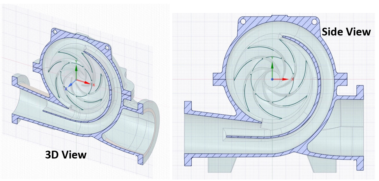
SpaceClaim also has convenient tools to simplify rounds, chamfers, and fix short edges. This helps to prevent mesh from clustering in these regions. It is also efficient at fixing any geometric irregularities that can get generated in scanned data. The video below shows an example of how such geometric defects can be fixed using SpaceClaim’s missing faces tool. At this stage, surfaces are created to split the domain into two fluid domains, one inside the impeller where the governing equations are solved in a rotating frame of motion and the other where they are solved in a stationary frame of motion. This split allows the simulation to be solved using a steady state approach.
The pictures below show screenshots of the final geometry supplied to Fluent meshing for mesh generation.
Mesh generation in Fluent Meshing:
Fluent meshing is the best in class meshing tool for fluid dynamic problems. Fluent meshing has workflows to address clean CAD generated in CAD packages, along with workflows to address CAD created through scanned data like the one at hand.
The Wrapping methodology is used for meshing this geometry as it is recommended for geometries created through scanned data. The geometry is imported into Fluent meshing using the CAD faceting option. Regions of intersection in the solid regions are identified and intersecting loops are created to increase the extent of feature capture in these regions. Sizing functions are then created to capture regions of curvature and proximity in the model. These size functions are used to create a size field which is central for the wrapping process. Material points are created to help the mesher differentiate between the stationary and rotating fluid zones.
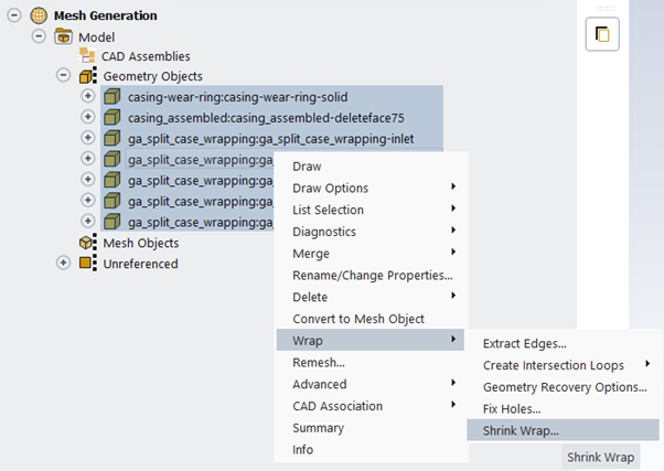
Once the size field and the material points are defined, the wrapping process can begin. Wrapping is done by selecting all the geometric objects, right-clicking and navigating to the Shrink wrap function as shown in the screenshot below. During the shrink-wrap process, users can specify a resolution factor of 0.75 to allow improved feature capture during the wrapping operation.
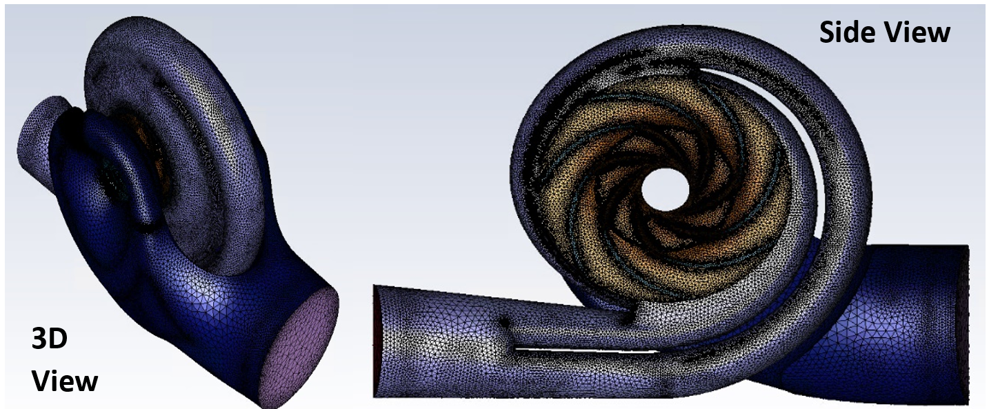
The wrapping process yields a closed surface mesh representing the fluid domain for each material point selected. As a result, the process needs to be repeated three times to generate the rotating fluid zone inside the impeller and the stationary fluid zones within the casing. The wrapped surface meshes created in Fluent meshing are shown below.
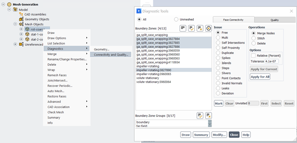
The quality of the created surface meshes can be improved by using the diagnostic tools. These diagnostic tools help improve the quality of surface mesh by collapsing highly skewed cells or by smoothing the nodes of skewed faces to reduce skewness. A maximum skewness of 0.7 is achieved for all facets on the wrapped surface mesh.
The inlet and outlet boundaries, along with the rotating walls are named appropriately and inflation settings are specified to create boundary layer cells adjacent to the walls.
The next step in the meshing process is to create a volume mesh within these fluid volumes. Fluid volumes are created using tetrahedral elements. The quality of the generated volume meshes is improved by using the “Auto-Node-Move” procedure. The final mesh is checked for quality and other metrics and is transferred to the CFD solver for setting up the simulation.
Simulation set-up in CFX-Pre:
CFX is the solver of choice to simulate the fluid flow in the pump. It is the best in class solver for simulating rotating machinery. The CFX solver has advanced features to model the flow through interfaces between the stationary and rotating fluid zones. The solver is easy to set-up and this set-up can be reused for subsequent iterations.
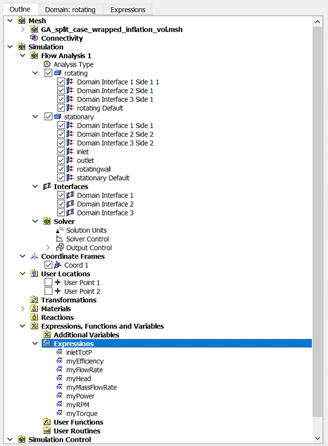
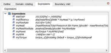
Expression language is another strong feature in CFX. Boundary conditions can be specified using expressions. A value for the total pressure is specified at the inlet and a mass flow rate is set at the outlet. The RPM of the impeller is also specified as an expression. In addition to input boundary conditions, CFX also allows output quantities of interest to be defined as expressions. The pump head, the efficiency and the power draw are quantities of interest from this simulation. Expressions are created for these quantities as shown in the screenshot below to monitor the values at solve time to determine convergence.
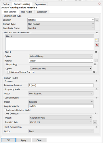
The fluid zone within the impeller is set as a rotating domain with the angular velocity expression previously defined. The walls of the impeller bounding the stationary fluid zones are also set with the same angular velocity from the expression. The interfaces between the rotating and stationary zones need to transfer the fluxes accurately between these zones for an accurate CFD simulation. This is done through a mixing plane model for the frame change between stationary and the rotational zones. This mixing plane model circumferentially averages the fluxes in bands and transfers the average fluxes to the downstream component and is ideal for simulating pumps and other turbomachinery applications.
The solver settings are specified as per the best practice and a physical time scale inversely proportional to the pump RPM is chosen to run the simulation. A solver definition file is created and transferred to the CFX-Solver manager to generate a converged solution satisfying the RANS equations for the input boundary conditions.
Solution set-up in CFX-Solver Manager:
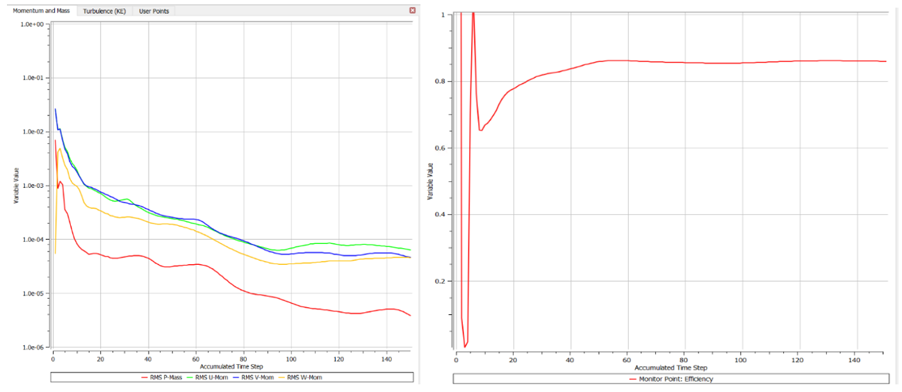
The definition file is created by CFX pre is loaded into the CFX-Solver manager and run until the residuals and monitors of interest flatline. The residuals drop by 4 orders of magnitude within 100 iterations. The monitor plot showing pump efficiency also flatlines after 100 iterations.
Post-process solution in CFD-Post:
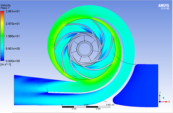
CFD post is the tool of choice for post-processing converged CFX simulations. CFD post allows easy creation of contours, vectors and streamlines to visualize flow patterns in greater detail. In addition, CFD-Post has a case comparison feature which can be used to compare the performance of various design iterations to choose the best candidate. The contours below show velocity field in the rotating frame of reference. The velocity increases with increasing radial distance from the impeller hub.
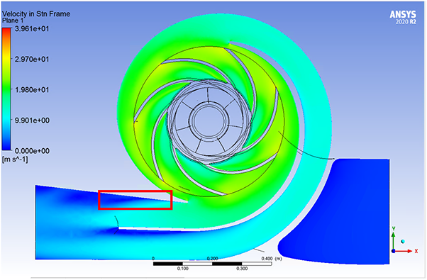
Contours below show the region of flow separation at the exit of the volute.
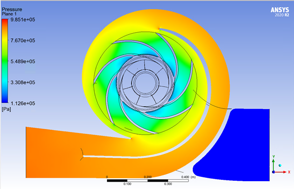
The figure below shows the contours of static pressure rise within the pump. The kinetic energy imparted to the fluid in the impeller is converted into pressure rise within the volute section.
In addition to qualitative information, CFD-Post can read expressions created in CFX-Pre and utilize them to provide quantitative estimates for pump efficiency, pump head and pump power from the converged simulation. The predictions from CFD yielded pump efficiency of 85.5% versus a test prediction of 85.7%. Close match between the CFD simulation and test result further validates the accuracy of Ansys CFD solvers in analysing complicated flow features within turbomachinery applications.
Conclusion:
The client was pleased to see how well results from Ansys CFD simulations matched their experimental findings. The ability of CFD simulation to clearly identify regions of flow separation was also in line with their expectations. This gave them confidence in using Ansys CFD simulation workflow to incorporate CFD into their design process.


