
Guest Blog by Renata Favalli, CFD Specialist, FCT Combustion
Use of Alternative Fuels (AF), such as biomass, has increased steadily over the past decades, and many cement plants across the world have adopted partial AF substitution into their pyro-processing operations. Adoption of AFs is driven by their wider availability and the lower cost of some AF sources, as well as environmental sustainability as the practice makes practical use of items that may otherwise go to waste.
Kiln and calciner burner systems have a major impact on the bottom-line results for a cement plant, and so customised optimisation of the flame for any given kiln is critical to get the best plant performance. In the quest to increase AF firing capabilities, a burner specialist such as FCT can assist plants to find an optimal design and tailored solution for their unique plant and environment.
At FCT, Computational Fluid Dynamics (CFD) simulations are a crucial tool used in the development of tailored burner design. The CFD modelling results provide accurate insights into flow aerodynamics which cannot be observed otherwise, and these results can be used to systematically optimise burner design to help achieve the important goals of:
- improved fuel efficiency,
- improved product quality, &
- increased production output.
"FCT is deeply thankful for the high-quality of LEAP’s technical support, especially with access to Prof. David Fletcher who we find is always ready to help – working above and beyond our expectations. His technical knowledge and experience in advanced combustion and turbulence modelling is unparalleled in Australia and of huge value to our work at FCT, and keeps us moving towards excellence in our pyro-processing CFD modelling."
Renata Favalli - CFD specialist, FCT Combustion
The case
A cement producer in Europe recently approached FCT to improve their AF firing rate involving coal and AF being fired in their kiln by a 30 MW burner. The rate of AF firing in the kiln was limited to 70% due to high CO levels. Even when firing 100% coal, the firing rate was limited by CO emission, which in turn limited the degree of calcination and overall plant capacity. Severe problems with build-up forming in the area above the kiln inlet chamber had also been identified. To remove this build-up, the kiln needed to be stopped for several hours roughly once every fortnight.
In-House CFD team at FCT
FCT has an in-house team of Computational Fluid Dynamics (CFD) specialists, who undertook a comprehensive study into the combustion environment with the kiln operating with the burner used at the time, followed by the operation using FCT’s Turbu-FlexTM with the same AF firing rate, as well as with an improved AF rate.
In every project, the existing configuration is always studied first. All information collected at the site survey, such as measurements, photos and observations from plant engineers, will then be used to check the modelling outputs and validate the results before any other scenario is considered. One thing that stood out during plant survey was the RDF particles hitting the kiln wall as soon as they were ejected from the burner, as it can be seen on the photo of Figure 1. There was no explanation at the time for such behaviour.
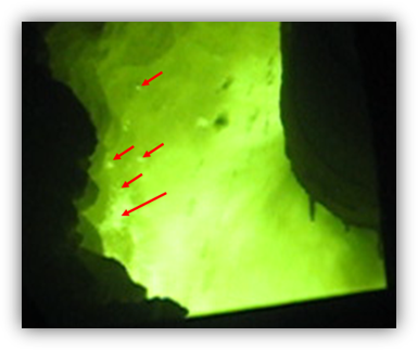
Figure 1: Burning RDF particles hitting the kiln refractory.
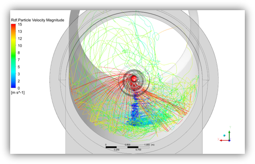
Figure 2: Fuel particle tracks obtained via CFD modelling of the original burner, demonstrating fuel particles hitting the kiln wall.
During the CFD modelling stage, the particle tracks, as shown in Figure 2, were reproducing the flight behaviour seen on site. It was later realised, through the CFD results, that there was an inconsistency between the swirl direction of the secondary air flow and the burner swirl/kiln rotation due to geometry and aerodynamics of the kiln hood and cooler, as sketched in Figure 3. It is rare for the secondary air flow and burner swirl/kiln to rotate in opposite directions, and this mismatch was causing the fuel particles to follow an unusual flight path and hit the kiln wall and material bed before complete burnout. This unexpected change in rotation direction of the secondary air cannot be directly seen or measured on site and it was unknown up to this point, until it was uncovered by our review of the CFD results.
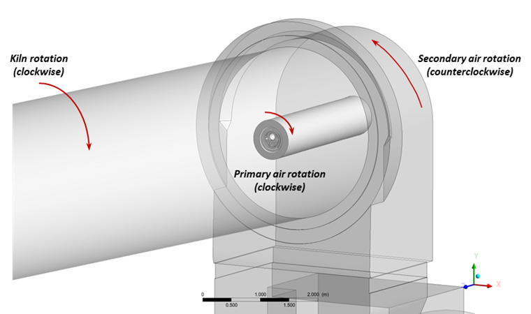
Figure 3: Sketched rotations of kiln showing the primary and secondary air flow directions.
The original burner design was not well-suited to the existing kiln conditions as it was a relatively low momentum burner, which meant the burner was unable to overcome the direction of secondary air rotation and could not keep fuel in suspension long enough to burn optimally. Fuel was also being directed towards the wall.
As a point of comparison, FCT also modelled the performance of the Turbu-Flex™ burner in the same conditions, i.e., with the burner swirl in the opposite direction to the secondary air rotation. The Turbu-Flex™ demonstrated better performance in these adverse conditions due to the burner’s high momentum design, which was able to overcome the cross-current and keep the particles away from the kiln walls.
An additional case was studied, matching the burner swirl and secondary air swirl rotation. Figure 4 compares the particle tracks for the Turbu-Flex™ in this condition with those for the original burner. Particles are kept in suspension over greater distances and the in-flight combustion of the fuel particles is maximised with the Turbu-FlexTM.
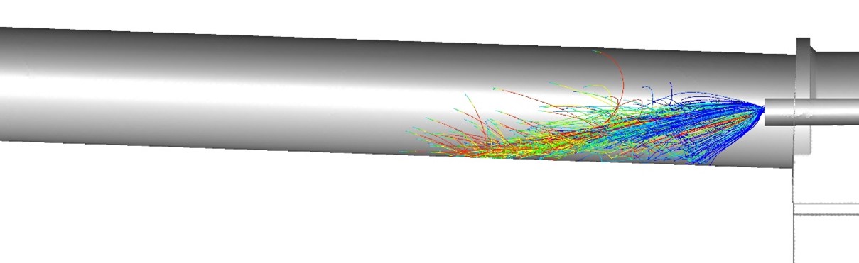
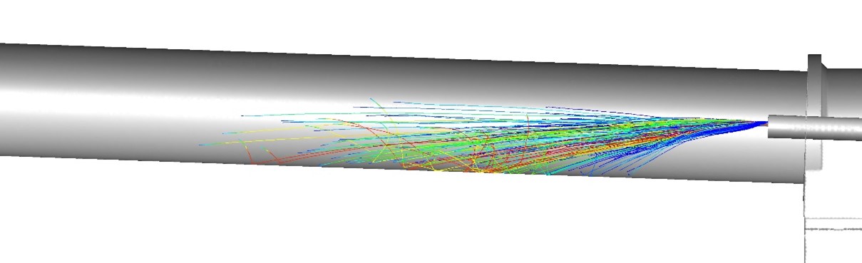
Figure 4: Comparison of original burner (top) and the Turbu-Flex™ (bottom). Particle tracks clipped at 5% residual volatile amount and coloured by particle mass.
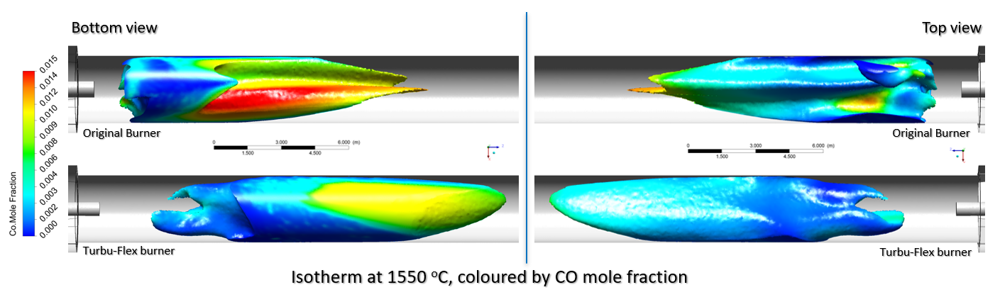
Figure 4B: Comparison of an isotherm at 1550 deg C (coloured by CO mole fraction) for original burner (top) and Turbu-Flex Burner (bottom) with view from both bottom (left images) and top (right images) of the kiln
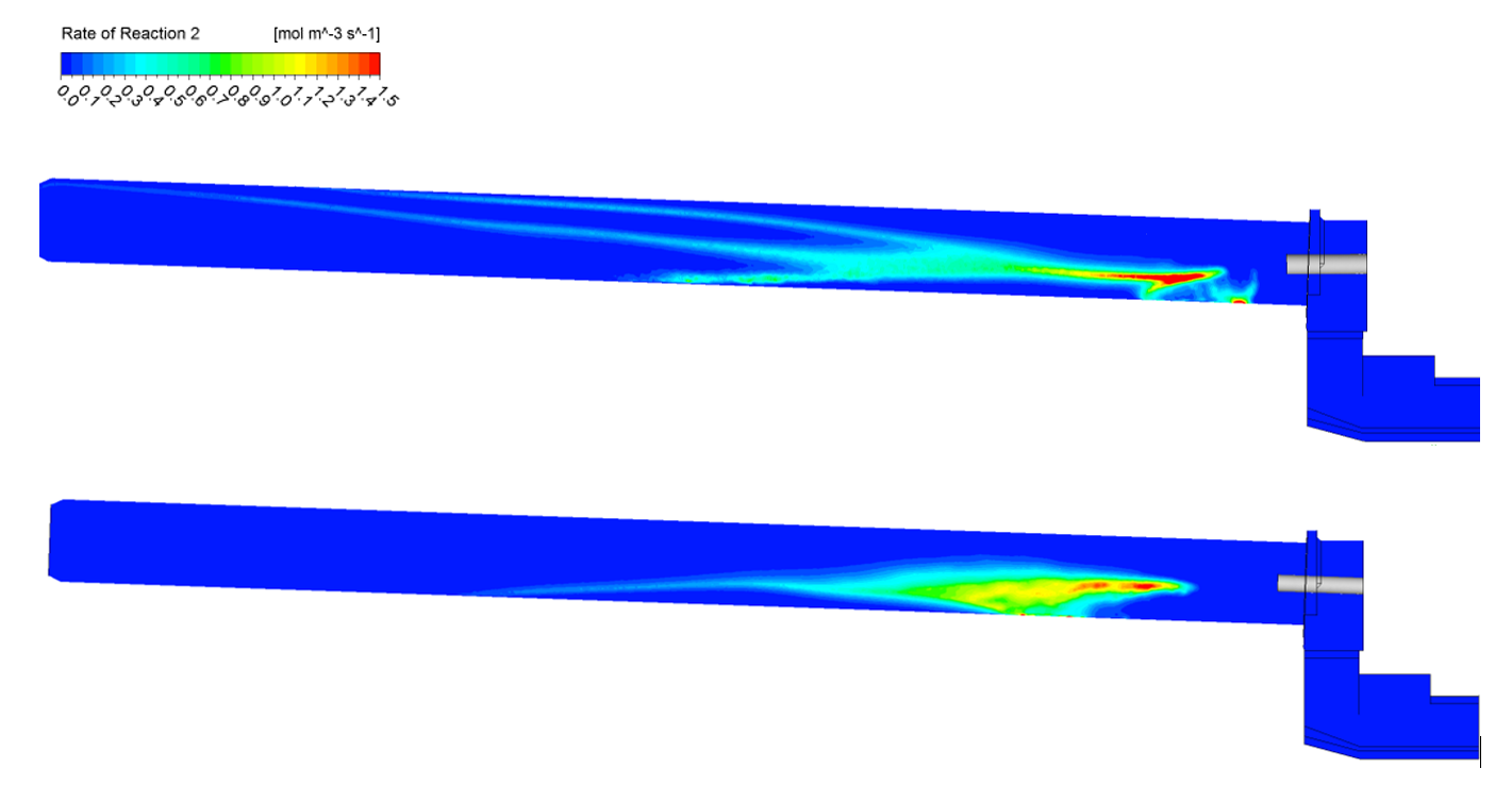
Figure 5: Comparison of the volatile reaction rate obtained on the kiln centre line plane for the original burner (top) and Turbu-Flex™ (bottom).
In addition to correcting the swirl direction and particle trajectories, FCT’s Turbu-Flex™ burner also provided an increased rate of secondary air entrainment and heat release from the particles. Figure 5 demonstrates the intense projection of part of the volatiles onto the kiln wall close to the discharge end (original burner) creating a reduction zone in this region which is then adjusted to be kept well centralised and away from the bottom for greater distances when using the Turbu-Flex™ burner.
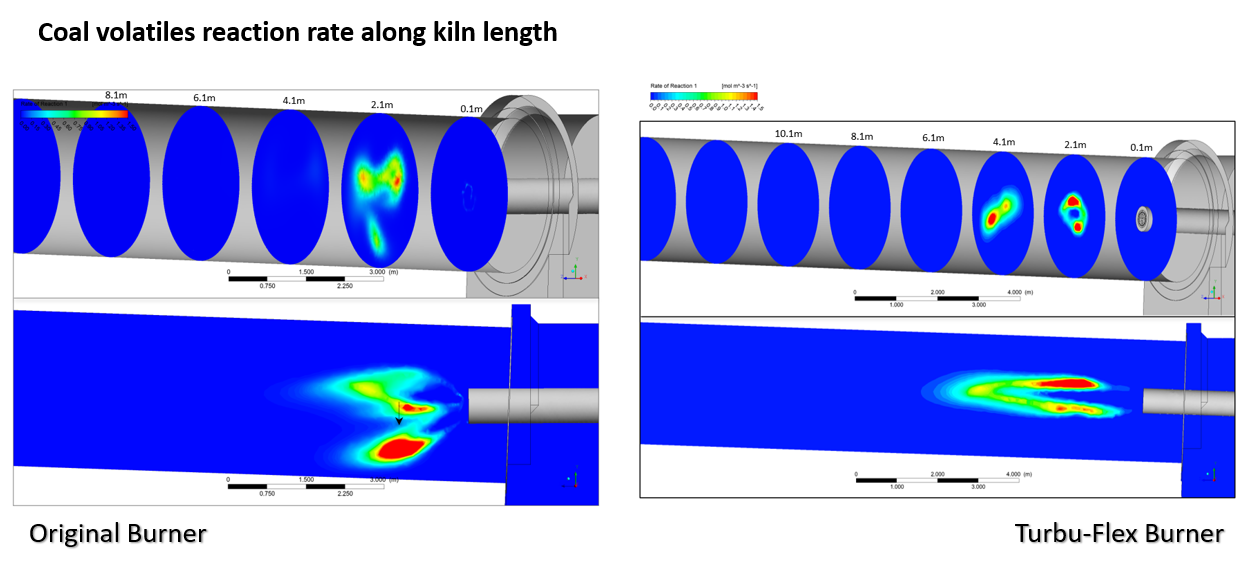
Figure 5B: Comparison of coal volatiles reaction rate along kiln length for original burner (left) and Turbu-Flex Burner (right)
The study formed part of a burner replacement programme. The results of these CFD simulations were used to optimise the performance of the new burner design.
Benefits of Turbu-Flex™
Based on the results of the CFD study, the original burner was replaced with the Turbu-Flex™ burner design, tailored for the plant’s specific environment and set-up. The Turbu-Flex™ burner design does not involve any moving parts and provides benefits due to easier maintenance.
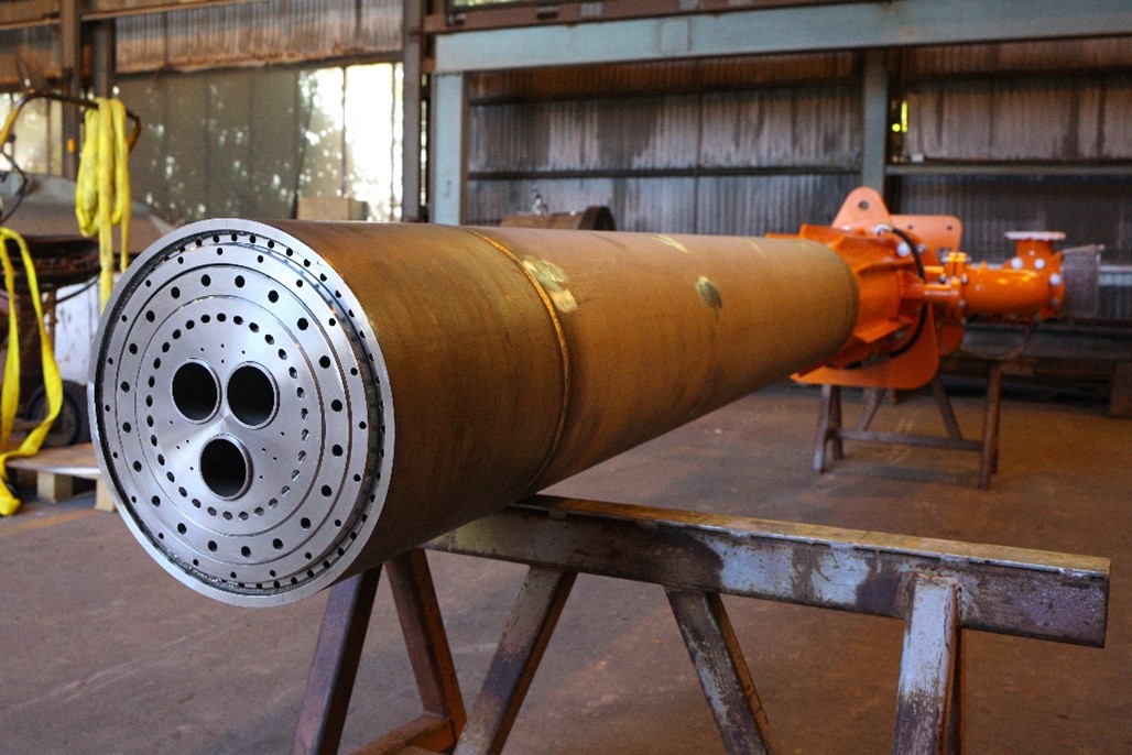
Figure 6: FCT’s Turbu-Flex burner.
Designed with flexibility in mind, a key feature of the Turbu-Flex™ burner is that the primary air axial holes are in two groups, each with a separate air supply. As demonstrated in Figure 7, the turn of a single valve switches the burner to operating in AF (alternative fuel) Boost Mode, where the configuration changes from the standard configuration of many evenly distributed holes all at the same pressure, to a smaller number of holes at high pressure grouped together.
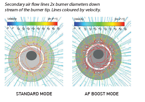
Figure 7: The smaller number of holes grouped together can be seen to increase the secondary air entrainment into the core of the fuel stream and peak flame temperature, making it ideal for co-firing with alternative fuels.
Results
The real-world performance of the Turbu-Flex™ burner was compared against the original burner over an equivalent 6-month period, measuring clinker production and clinker quality as two key performance indicators. The benefits of the new burner, as outlined in the results below, resulted in a Return on Investment of around one year when considering:
- Increase in clinker production (considering larger cement sales volume as well as higher costs for CO2)
- Reduction in kiln specific heat consumption
- Reduction in CO emissions
- Changes in NOx emissions
- Higher AF substitution rate
Clinker Production
Turbu-flex™ was found to operate with less CO content at the kiln inlet for the same exhaust fan settings, providing the potential to increase the kiln feed rate, and thus increasing the output of the kiln.
The kiln is now able to be operated at maximum production rate as allowed by the ID-fan and the new burner has allowed the hourly output of the kiln to increase by 0,91 t/h (increased by 1,8%) of clinker. When considering the additional benefit of superior operational stability of the new burner (increased by 2,9%), the yearly clinker production increased by 4,8%, as outlined in Table 1.
| Operating hours | Clinker (t) | Production (t/h) | |
| Original burner (6 months in 2019) | 3,827 | 191,484 | 50.03 |
| Turbu-Flex™ (6 months in 2020) | 3,939 (+2,9%) | 200,650 (+4,8%) | 50.94 (+1,8%) |
In this case, the application of CFD provided crucial and otherwise hidden insights into the combustion environment. This knowledge positively contributed to real-world burner optimisation that allowed FCT’s client to increase AF substitution, while also solving the costly issue of kiln build-up which was causing the plant to shut down for several hours every fortnight.
The implementation of a specialist burner design, informed by these CFD results, enabled FCT’s client to improve clinker quality and production while experiencing quick return on investment.
Find out more about FCT Combustion and see more examples of their recent projects at their website here.


