
This blog provides a summary of Conflux’s presentation at the 2021 Australasian Ansys Fluids user group hosted by LEAP Australia.
The technical team at Conflux Technology consists of a mix of design engineers, simulation experts and additive manufacturing specialists who are creating cutting-edge heat transfer solutions with the aim of revolutionising the heat exchange technologies used across the aerospace, defence, industrial, energy, automotive and microelectronics industries.
The design process at Conflux usually starts with analysis. The initial analysis involves empirical calculations in Excel to help scale and size what we think the core is going to look like and determine what the sensitivity is to different parameters. Then we break down the 3D analysis into regions of periodic boundary conditions, where possible, and undertake some iterative development to reach the heat rejection and pressure drop performance we are targeting. This is achieved by doing thermal and flow analysis inside Ansys Fluent and CFX and then we use that to visualize the results and understand what might be limiting our performance or unnecessarily increasing our pressure drop. Then we move on to manifold design which considers build direction and mounting which leads us on to structural analysis for various load cases. We make sure it can survive any required loads for the component including shock and vibration, pressure and creep-fatigue predictions if necessary.
At Conflux, we run most of our simulation internally with our in-house cluster which allows us to simulate CFD models with hundreds of millions of mesh elements. If we need to run larger simulations, we do have external computing resources we can utilise.
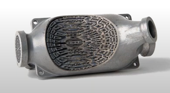
Figure: One of the original parts developed by Conflux founder, Michael Fuller, is shown below - cut open to show the intricate internals with the heat exchanger
With our designs, we have a design library containing standardized cores geometry which we can utilise as a starting point of analysis. We can leverage Ansys Workbench to automate the process of generating named selections, selecting the right meshing parameters and generating the mesh from parametric CAD models. Then within Fluent we can use parameters to set the number of sub cores that would make up the heat exchanger and we can change that number rapidly and that can impact the flow rate through the sub core, allowing us to then set other things such as the overall heat exchanger flow rate and inlet temperatures. These results are then used to calculate the overall heat exchange for the heat exchanger, based on the sub core value as well as the overall pressure drop. We have a database of thermal-physical properties for water glycol mixtures, EV coolants, engine oils, fuels and refrigerants and draw on them as required.
In the image below you can see several examples of geometries we utilise for analysis. Using the ANSYS simulation package, we run a variety of different points for a single bit of geometry and using empirical analysis we can predict what changing the length of the coil will have, and what changing the frontal area of the core will have. You can see in the images below, we can evaluate how in this case if you want to have a constant pressure drop, what effect the length has to change and we look at if we want to have the surface area constant, what the size of the whole component has to be geometrically and then we can find the optimal crossover point which will achieve the target pressure drop and heat transfer surface area.
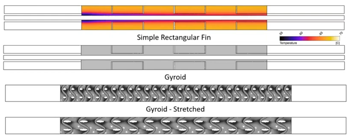
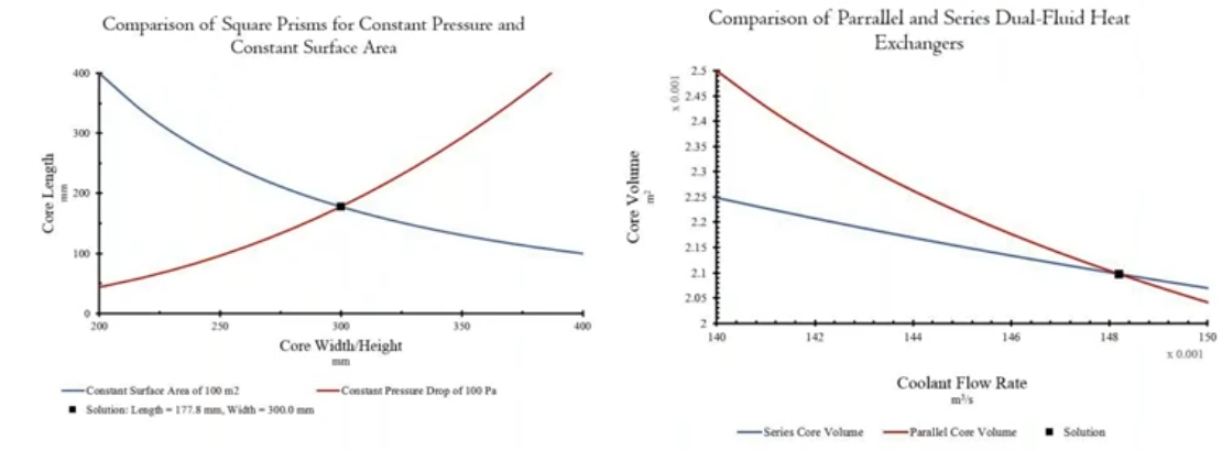
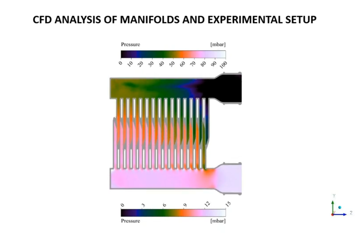
Figure: CFD results showing pressure distribution within a manifold
We also post-process with streamlines and here in this image you can see the variation in pressure as we move through an example heat exchanger design. Those pressures can create non-uniform flow through the manifolds, where you can observe less flow down tubes that are further away from the inlets.
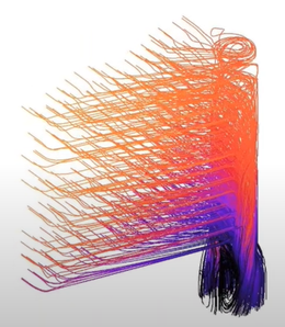
Figures: Streamlines coloured by total pressure
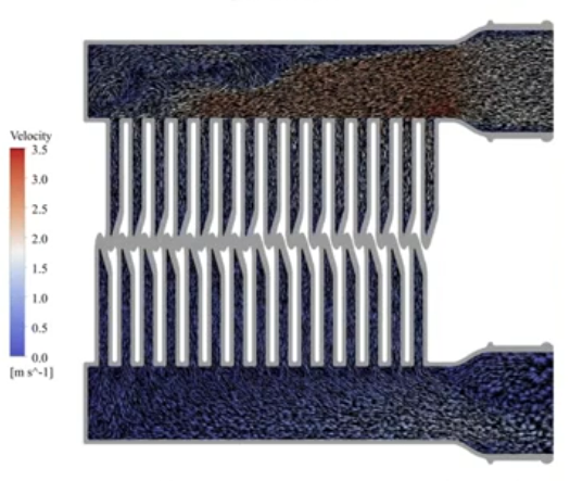
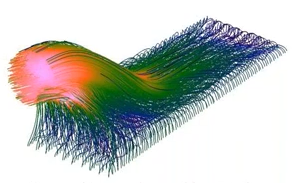
Figure: Surface velocity vectors coloured by velocity magnitude
Once we've completed these designs, we send our components off to be tested. The image below shows a test setup of that original component and when we test we have to correlate back to our CFD results. We continually improve our predictive accuracy for heat rejection, pressure drop and durability through iterations of first principles calculations, multi-physics simulation and physical testing.

To learn more about Conflux Technology, please visit their website and we recommend you also follow them on LinkedIn to stay in touch with future announcements in this space.


