
Tunnels have been a feature of road and rail infrastructure for over 150 years in Australia and New Zealand. From the first rail tunnels of the 1860s at Mereweather NSW and Lyttleton on New Zealand’s South Island, to the upcoming opening of NorthConnex west of Sydney which, at nine kilometres long, will claim the title of longest road tunnel in Australia, road and rail tunnels will continue to be a feature of future government ‘congestion busting’ infrastructure programs.
Importantly for engineers working on these massive infrastructure projects, tunnels must be designed to prioritise the safety and comfort of passengers and motorists. Their enclosed nature means that adequate ventilation must account for maintaining acceptable air quality and temperature, both under normal operation and during unscheduled events, such as service interruptions or accidents.
As a tunnel increases in length, the requirement for forced ventilation, often using devices such as jet fans, increases. The selection, number and placement of this equipment depends on scores of factors that include the tunnel geometry, sources of emissions and heat, and building regulations.
Projects must also be economically viable, which requires engineers to optimise the balance between upfront costs of equipment/installation whilst minimising ongoing operating expenses. A 2017 World Road Association (PIARC) study indicated that the design phase of road tunnel projects has a 60-80% impact on total operating costs, which is much higher than any other phase.
Simulation has a vital part to play in the design phase of almost all infrastructure projects. The ability to test various design configurations and verify performance virtually, without build-and-test methodology, allows significant cost savings and faster project delivery.
At LEAP Australia, we have helped our clients’ solve HVAC problems across a wide array of infrastructure projects, using Ansys simulation software to rapidly provide project teams with accurate simulation results for various design scenarios that are being contemplated.
Whether we begin the geometry phase with existing 3D CAD or are working from plan drawings, ANSYS SpaceClaim is a very effective tool to quickly clean up or construct geometry, with a suite of repair features and direct copy/paste of dimensioned features from plans.
The watertight meshing workflow in ANSYS Fluent makes use of a rapid, easy to use system that has the advantage of building meshes exclusively for CFD. As a result, the mesh quality for challenging cases is often high enough to transfer to the solver without any need for user modification or smoothing.
The ANSYS Fluent solver is industry-leading, and its accuracy has been trusted for many years. Further improvements to its user experience have significantly reduced the learning curve for new users. The scalability of the solver allows the largest problems to be solved quickly on multiple CPU cores, and parameterisation features enable solving many different design points, often simultaneously.
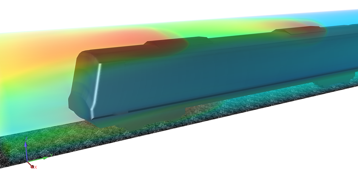
ANSYS EnSight can provide convincing and appealing images and videos to help you clearly communicate the meaning of your CFD results. Custom textures, moving camera tracking and streamline animations are just a few of the features we use in our reports. These benefits allow a reader not familiar with CFD to clearly understand the important data from our solutions.
Here in this 'meet the expert’ series we learn from Dave Hyde at LEAP with some insights from a recent CFD project for a rail tunnel.
What happens when a train is halted for long periods away from a platform?
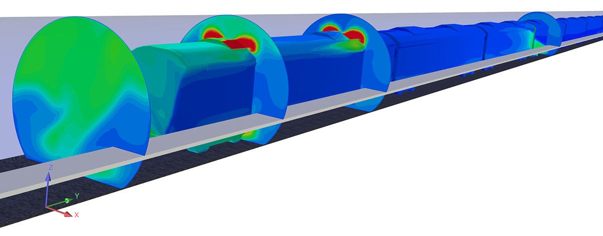
For trains that need to make unscheduled stops inside tunnels, the main concerns for passenger trains are thermal comfort and safety in cases of emergency. In a recent project we completed, the client needed to understand whether the roof-mounted air conditioning condensers would be drawing back in the hot air that they exhaust. This can reduce the performance of the condensers and lead to higher temperatures in the train cabin.
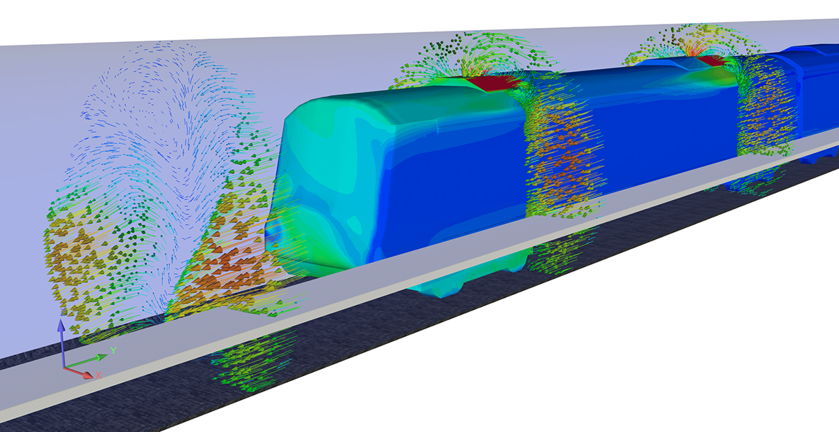
CFD allowed us to predict the flow fields around the condensers, which have inlets and exits in close proximity. We found that the present implementation of vent louvers to direct hot exhaust flow to the sides of the train resulted in a low amount of hot gas being ingested into the inlets, which were drawing in air from the centre of the tunnel. Had we found problems, it would have been easy to run a series of simulations to experiment with different louver positions or different inlet and outlet locations.
How are condenser exhaust and inlet details accounted for?
When studied as part of an overall system, condenser details are often simplified to speed up delivery of CFD simulations. Simplifications include removing detailed geometry, but consulting with clients to obtain correct operating values for the units so that we can still account for their influence on the problem. One example is to replace a fan with a fan curve or a condenser with a porous zone. Sometimes it can be also acceptable to use an inlet/outlet pair of boundary conditions, using known flow rates and temperatures.
How is a typical jet fan modelled within the tunnel?
The way that jet fans are modelled in CFD depends on the application. Detailed machine characteristics can be understood for jet fan manufacturers using CFD tools. As part of a tunnel ventilation study, generally the equipment has been selected and operating characteristics are understood, meaning that the fans can be simplified. Fan data is often supplied as a curve relating pressure rise to flow rate, and it is trivial to include this data in our simulations.
Why was post-processing done using Ensight?
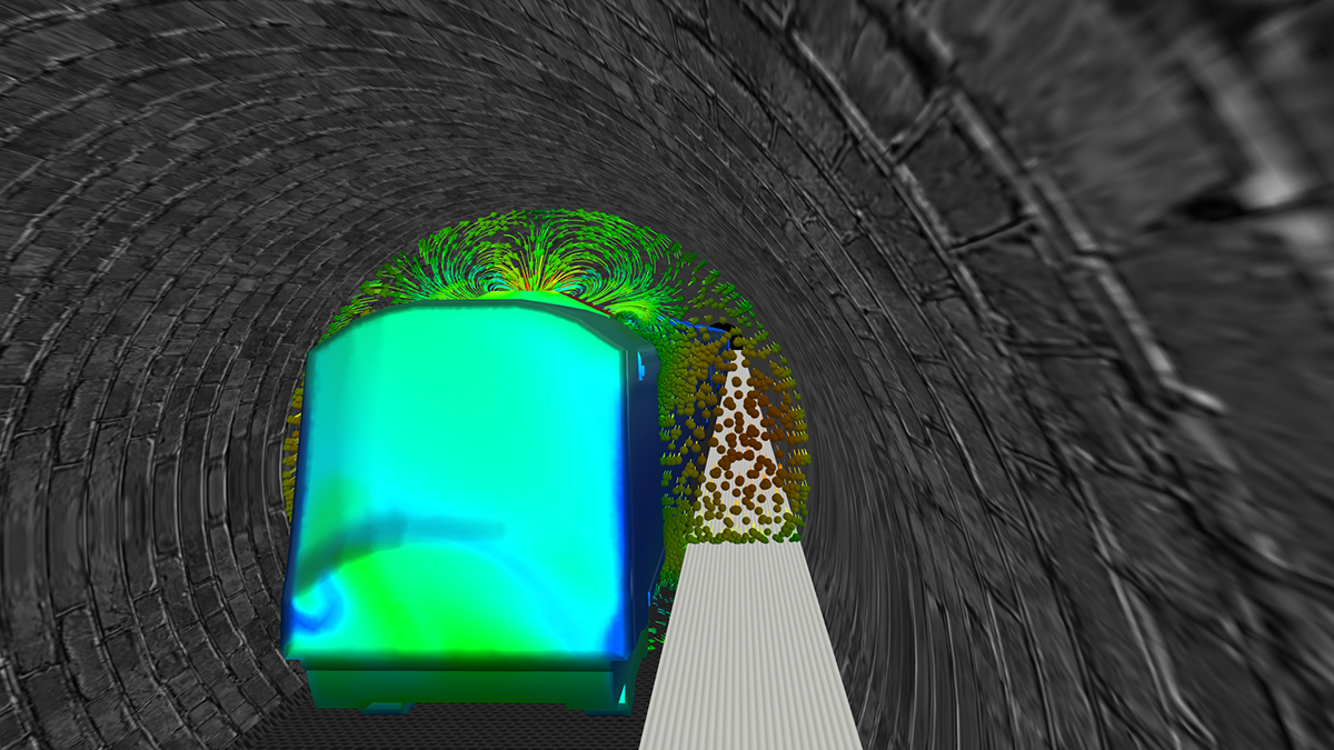
EnSight is the gold-standard for CFD post-processing and offers a number of attractive features. In this recent tunnel project, we used the custom texture processing feature in EnSight to give the tunnel and walkways a more realistic look. The streamline animations, which can be created for steady state and transient data, offer a powerful way to see repeated injections of particles and their interactions with the structures they impact and how they are accelerated and slowed. We also made use of different light sources to bring emphasis to plots of interest, and the ability to have the camera transition along a path greatly helps to offer a virtual reality fly-through. These elements help the CFD analyst, often working from a limited number of basic plots and calculated values, communicate complex information to non-CFD experts such as management and customers - helping them understand how a product or process behaves in a way that is visually appealing and easy to understand.


