
Guest Blog by Luke Pollock, UNSW ADFA
Hypersonic vehicles are a special kind that can travel faster than five times the speed of sound, or approximately 1.5 km/s when flying at the normal altitude of a commercial jet. An aircraft like this could take you from Sydney to London in as little as 4 hours, about the same amount of time it would take to fly from Sydney to Darwin. So, the big question is, why aren’t we all flying on a hypersonic airliner right now? As you might imagine, the problem is not quite that simple. Hypersonic aircraft are exceptionally difficult to engineer and costly to build. Like the sound barrier that a supersonic aircraft must compete with, a hypersonic aircraft faces an altogether new challenge, the heat barrier. Some of the kinetic energy flying at these speeds is converted into friction and subsequently, heat, through the boundary layer. Whilst some of this heat is radiated or carried away by the flow a large part is absorbed by the vehicle itself, making it incredibly hot.
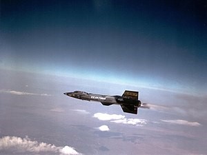
Figure 1. North American X-15 aircraft
The North American X-15 aircraft shown in Figure 1, which remains the fastest manned aircraft ever flown, could reach temperatures up to 700°C, high enough to melt the aluminium alloys used on today’s airliners. Because of these extreme temperatures, exotic materials must be used such as titanium or nickel-based super alloys. At even higher temperatures, metals must be replaced by pure carbon or an ablator, which erodes away during the flight, carrying heat along with it.
So, whilst we could choose to make our vehicle out of a titanium alloy that wouldn’t melt at 700°C, we have to contend with a new challenge – weakening.
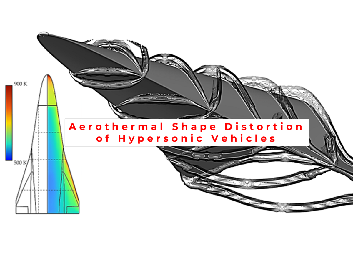
We know that these metals exhibit a gradual decay in strength and stiffness as the temperature increases, similar to what is shown in Figure 2. This weakening of the material, along with the pressure loads from flying so fast, cause the aircraft to distort and change shape. This effect is rather unique to hypersonic vehicles and is usually referred to as aerothermal shape distortion, aerothermoelasticity, or fluid-structural-thermal interaction (FTSI). The more modest effects from aerothermal shape distortion are changes in a vehicle’s aerodynamic performance. The more extreme is catastrophic failure. Modelling and understanding the aerothermal shape distortion is a key step in designing a hypersonic vehicle. Engineers must use tools that can not only simulate the aerodynamics but the thermal and structural response as well. The Ansys software package is one such option for simulating this multiphysics behaviour that is used by our group at UNSW Canberra.
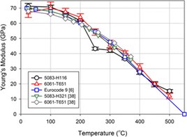
Figure 2. The relationship between stiffness and temperature for aluminium alloys (Summers et al., 2015).
As part of a project sponsored by Lockheed Martin Australia, I explored the effects of aerothermal shape distortion upon a representative hypersonic glider using Ansys simulations. The project aimed towards developing and improving multiphysics modelling workflows as well as quantifying the effects of aerothermal shape distortion for vehicle designers. The vehicle that we studied was developed by optimising the external geometry to provide the best aerodynamic features at the design condition. The internal geometry was kept simple with a solid tungsten nose to act as a ballast, and equidistant spaced frames made from a uniform thickness titanium alloy as shown in Figure 3.
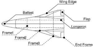
Figure 3. The layout of the representative hypersonic glide vehicle.
The workflow as established in Figure 4 aimed to take the flight condition along with the vehicle geometry and structure and through a process called two-way coupling, determine the steady-state performance of the vehicle as a result of aerothermal shape distortion.
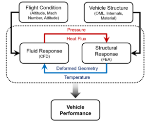
Figure 4. The two-way coupling methodology used to determine the effects of aerothermal shape distortion.
Ansys Fluent’s mosaic meshing was used to generate a poly-hexcore mesh which is shown in Figure 5. This new kind of mesh can be generated rapidly on multiple cores and has lower memory overheads than similar methods. The poly-hexcore mesh generates a hexahedral core in the bulk of the domain whilst using polyhedral cells to map topologically complex surfaces. In this project, the Fluent pressure-based solver with coupled scheme was used to resolve the fluid domain.
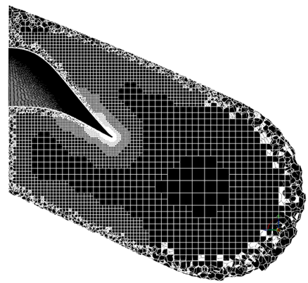
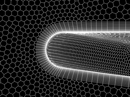
Figure 5. The poly-hexcore mesh used to model the external aerodynamics of the vehicle.
Whilst density-based solvers are typically used for high-speed flows, the project examined the merits of the pressure-based solver and found that it typically provided greater robustness and faster convergence whilst remaining accurate when compared to the density-based solver. Viscous simulations were performed using the Spalart-Allmaras (SA) one-equation turbulence model. The SA model has been extensively used and validated in the literature for attached external hypersonic flows and has been shown to accurately predict wall heat fluxes when the boundary layer mesh has a y+ value less than three. In this case, the mesh was generated such that the y+ value was less than one everywhere on the body. Spatial discretization was done using the schemes shown in Table 1. Steady-state solutions were obtained using pseudo-transient time stepping.
Table 1. Spatial discretization schemes used for the fluid simulation in Fluent.
|
Spatial Discretization |
|
| Gradients |
Least squares cell based |
| Pressure |
2nd Order Upwind |
| Density |
3rd Order MUSCL |
| Momentum |
3rd Order MUSCL |
| Modified Turbulent Viscosity |
3rd Order MUSCL |
| Energy |
3rd Order MUSCL |
Two methods were explored to model the thermal solution, conjugate heat transfer (CHT) and linear volume interpolation (LVI). CHT solves the conduction in the solid domain with the radiation at the wall and convection in the fluid simultaneously, obtaining a very accurate solution which is shown in Figure 6. Alternatively, LVI was explored wherein an empirically determined heat transfer coefficient was used to determine the skin temperature of the body. Following this, the internal temperature was found by linearly interpolating through the volume of the vehicle. It was found that LVI provided good approximation of the body temperatures at reduced computational cost and required less setup time. LVI was useful in this case because only steady-state conditions were being examined and its usefulness in a transient solution would need to be re-examined.
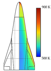
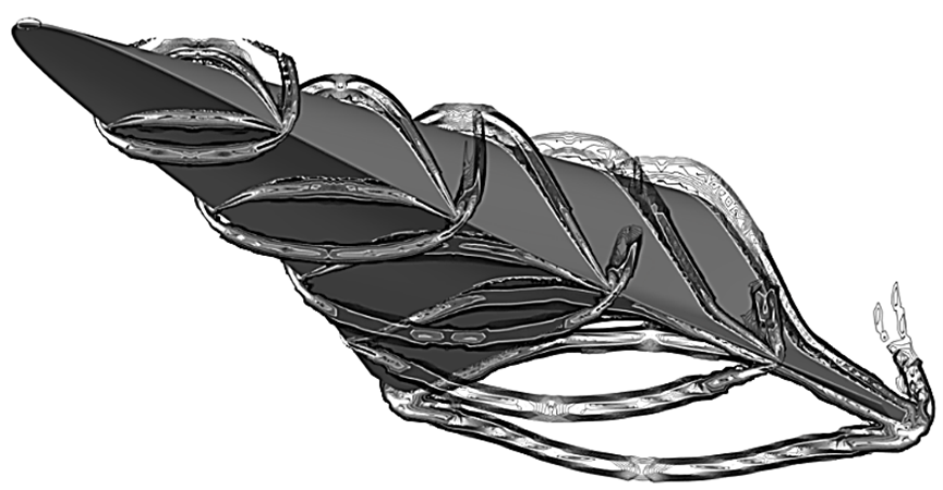
Figure 6. The wall temperature field and shockwaves obtained from the fluid simulation.
Pressure and thermal loads could then be imported into Ansys Mechanical APDL using Ansys Workbench System Coupling. These loads, along with appropriate boundary conditions, provided an estimate of the aerothermal shape distortion. The distorted geometry could then be re-meshed and solved in Ansys Fluent using Workbench System Coupling. The difference in aerodynamic metrics between the two solutions, shown in Figure 7, indicates the change in performance as a result of aerothermal shape distortion for this representative vehicle.
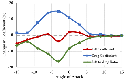
The multiphysics workflow implemented in Ansys ultimately showed that, when accounting for aerothermal shape distortion, the profile drag was found to have increased by 13.4% whilst the maximum lift-to-drag ratio decreased by 4.6%. A study of aerothermal shape distortion upon the vehicle’s control surfaces showed an 8.4% decrease in effectiveness and a 14.2% reduction in the static margin. Whilst these effects could be quantified, many modelling assumptions were made along the way to reduce complexity and computational cost in the pursuit of obtaining an engineering-ready solution.
The field of hypersonics is a booming one and will require creative engineers skilled in the art of numerical modelling to design the hypersonic airliner of tomorrow. Scholarships are available for domestic and international students to study at UNSW Canberra. Visit https://www.unsw.edu.au/canberra/study-with-us/scholarships/postgraduate-research-scholarships for more information.
More information can be found in Pollock, L., Moran, J., & Neely, A. J. (2023). Effects of Aerothermal Shape Distortion on Hypersonic Vehicle Performance in Cruise. In 25th AIAA International Space Planes and Hypersonic Systems and Technologies Conference. American Institute of Aeronautics and Astronautics. https://doi.org/10.2514/6.2023-3033.
This research was supported by Lockheed Martin Australia. Any opinions, findings, and conclusions or recommendations expressed in this material are those of the authors and do not necessarily reflect the views of Lockheed Martin Australia. Numerical resources were provided by the National Computational Infrastructure (NCI) under the National Computational Merit Allocation Scheme (NCMAS).


