In our previous post we discussed the importance of geometry preparation, utilising the ANSYS Global Mesh Control settings and the best use of the ANSYS Meshing Advanced Size Functions. We will now focus on the ability to target specific areas of the mesh for additional refinement and mesh control, which is recommended for intermediate to advanced users.
[box] By using these explicit sizing controls, the resolution of the geometry can be accurately captured and we can ensure that we accurately resolve any high gradient areas in the flow, such as a wake or separation/recirculation zones.[/box]
As you would expect, in addition to the automated settings, ANSYS Meshing provides users with as much additional control as they desire: with the option to specify combinations of point controls, edge controls, surface controls and/or body controls. Each one of these has its own options and can be used to influence the mesh in different ways.
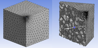
Point controls can be used to control the mesh based on a sphere of influence, whereby any region of the mesh that is contained within the sphere will be given the chosen sizing. An example of this is shown below.
Point Sizing (using Sphere of Influence)
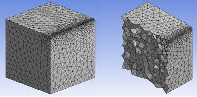
Edge Sizing Controls can be given to any edge and allow for different types of bias control, whereby the mesh size varies along the edge. In the image below, we have applied an edge sizing to a single edge.
Basic Edge Sizing
The edge sizing feature can use either a specified element size, a number of divisions along the edge or can be controlled by a sphere of influence. This last option will refine along the edge only where it is intersected by the sphere of influence, and we will show this later on in this blog post.
Within the edge sizing function, you have the ability to set a local growth rate for all cells that grow away from this edge (overriding the global growth rate). There are also useful options for Edge Bias control, which allows you to define how the mesh is distributed along the length of the edge. For example, you can force the mesh along the edge to vary from large to small, small to large; or more complicated bias such as large to small in the middle then back to large, or small to large in the middle and then back to small again at the other end of the edge.
So it is clear that there are quite a few options available to control edge meshing, and since it is such an easy tool to use, we'd suggest that you simply have a play around in ANSYS meshing to get a better understanding of how this works.
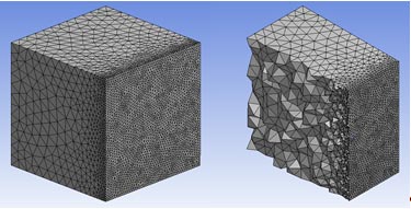
Face Sizing in ANSYS Meshing is also just as intuitive. We can easily apply a face sizing to any given face, or groups of faces, to control the mesh size on those particular faces. This is one of the more common ways that you can control the mesh and ensure that you are getting a consistent, high-quality mesh sizing in your desired regions. As before, we can also set the local growth rate, which will affect how fast the mesh will grow away from the face.
Face Sizing
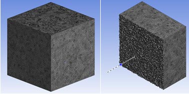
Finally, Body Sizing which allows you to add a sizing to an entire selected body or bodies. This will essentially overwrite the global controls that have been specified and is useful when you have multiple bodies and need to control the sizing in certain bodies individually. This may be the case if you need different quality meshes in solid and fluid components for a conjugate heat transfer problem, where you will need to accurately resolve the flow and thermal boundary layer in the fluid domain (which are essential to accurate calculations of the heat transfer), but can afford to tolerate a lower fidelity mesh in the solid components.
The Body Sizing function also has the option to set a growth rate. This will use the global values by default, but we can also define a local value which overrides the global settings and gives us individual control over the mesh for multiple bodies.
Body Sizing
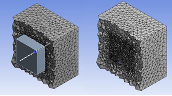
The Body Sizing control also has the ability to use geometric bodies themselves to control the mesh refinement (in ANSYS Meshing terminology, these are termed a "body of influence"). A body of influence can be of any arbitrary shape/size and intersects the main fluid domain that we are trying to mesh. In the intersection region, the ANSYS mesher will use this body of influence to create the right amount of local mesh refinement. This smart feature also removes the need to decompose the main body into complicated sub-regions. We have found this to offer great benefits in many cases, such as when setting up wake refinement regions in external aerodynamics problems.
Body Sizing using Body of Influence
We should also point out that some experienced users of ANSYS CFX-Mesh prefer the methodology using a "sphere of influence" scoped to edges, faces and bodies. This is still possible within ANSYS Meshing, but the trick is that you need to turn off the Advanced Size Function if you are trying to scope this to edges and faces. Whilst the sphere of influence is still a useful tool in some circumstances, I would be wary of turning off the advanced size function when you can use some of the other sizing controls that I’ve shown you above to achieve the same effect but still retain all the benefits of using the Advanced Size Functions in ANSYS Meshing.
Sphere of Influence on Edge, Face and Body
In our next post, we will review the Sweep Meshing method in ANSYS Meshing. In the mean time, remember if you have any questions then please contact the LEAP Support Team.


