
With a better understanding of the boundary layer in Part 1 of our series on Y+, let us look at a case study by varying the first prism height.
The model chosen below is a 2D multi-section wing in ground effect, uses the k-ω SST turbulence model and 2nd order schemes to solve the flow equations. The CFD geometry consisted of a large domain and two refinement domains. Pictures of the mesh for cases using y+ ~ 1 (top left), y+ ~ 30 (top right), y+ ~ 60 (bottom left) and ~ 100 (bottom right) are shown below in Figures 4-6.
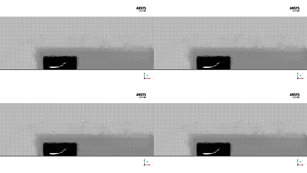
Figure 4 – View of the full flow domain, y+ ~ 1 (top left), y+ ~ 30 (top right), y+ ~ 60 (bottom left) and y+ ~ 100 (bottom right)
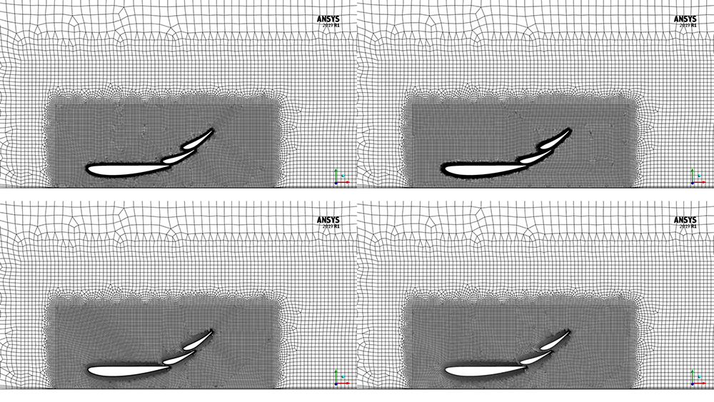
Figure 5 –Zoomed view showing the inner refinement domain
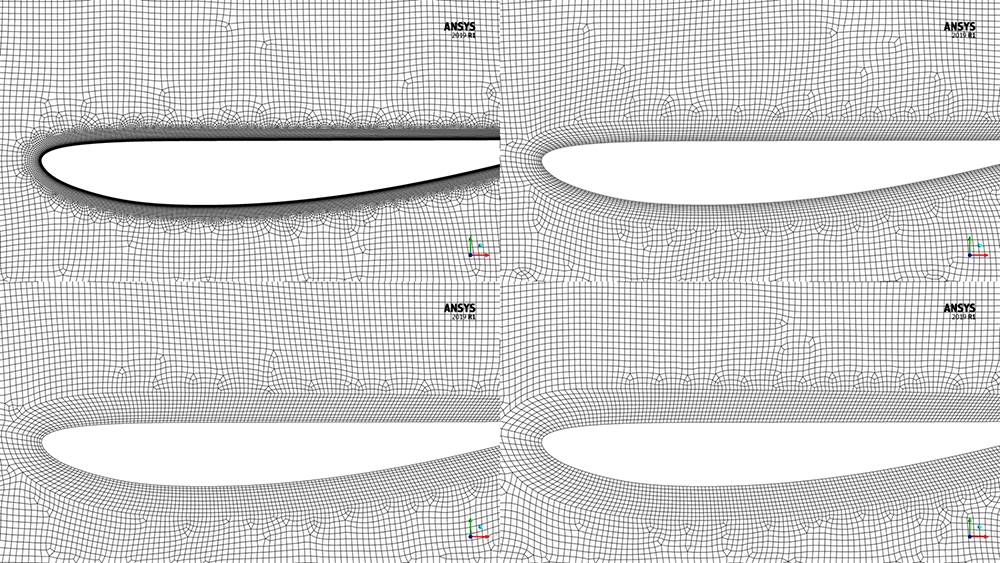
Figure 6 – Zoomed view showing the main section of the wing
The resulting velocity magnitude contours are shown below in Figures 7 and 8. Even though the prism heights are different, the bulk flow features are captured on all meshes. The wake region has the same shape and size, and the local acceleration of the flow around the wing sections is very similar.
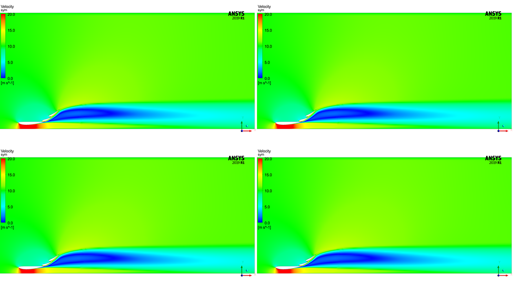
Figure 7 – Velocity magnitude distribution over the entire domain
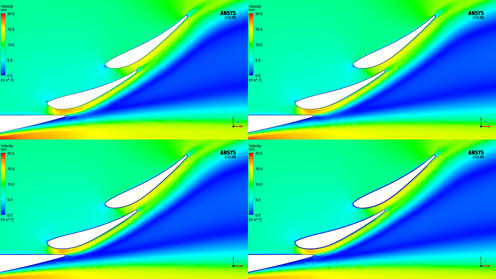
Figure 8 – Zoomed view of the velocity magnitude in the region of the flaps
The boundary layer profile, towards the trailing edge of the main section, along the red line, is shown in Figure 9. As a reminder, y+ ~ 1 resolves the full boundary layer profile and the y+ ~ 30, y+ ~ 60 and y+ ~ 100 use wall functions.
Comparing with the y+ ~ 1 case, y+ ~ 30 initially follows a similar shape and then deviates slightly, whereas y+ ~ 60 and y+ ~ 100 deviates much more. As mentioned in Part 1, better resolution of the boundary layer profile allows better prediction of the effect of the adverse pressure gradient, separation, surface pressure and therefore, force.
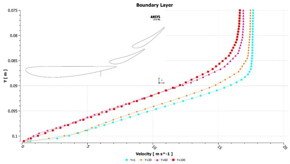
Figure 9 – Velocity profile normal to the wall on the main section towards the trailing edge
Wall shear stress, shown in Figures 10 and 11, on the main section can be used to predict separation as it changes with local velocity and tends to zero when flow separates. Figure 10 shows the results for the full wing and zooming in towards the end in Figure 11, shows a better picture of where separation occurs.
In this case, you can see that y+ ~ 1 and y+ ~100 by coincidence share a similar separation point, y+ ~ 60 and y+ ~ 30 separate 20 mm either side. On a 400 mm main section, comparing y+ ~ 1 with the other cases shows separation can be modelled within a fair margin.
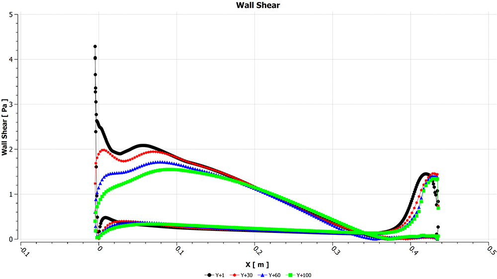
Figure 10 – Wall shear stress plot for the main section of the wing
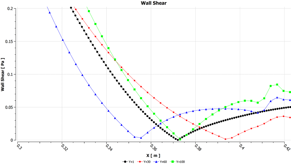
Figure 11 - Wall shear stress on the main section, zoomed view towards the trailing edge
Static pressure on the main section is shown in Figure 12. As y+ ~ 1 resolves the viscous sublayer, it has the most accurate surface pressure readings. With a y+ ~ 30, the surface pressure is close to y+ ~ 1 indicating similar forces. The y+ ~ 60 and y+ ~ 100 cases show a 50 Pa difference of the lowest static pressure on the wing, affecting force values.
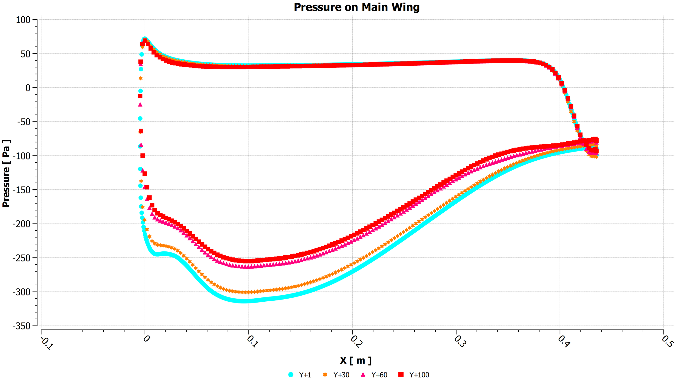
Figure 12 – Static pressure on the main section of the wing
Plotting static pressure on the symmetry plane, presented in Figure 13, shows similar static pressure around the main section for y+ ~ 1 and y+ ~ 30.
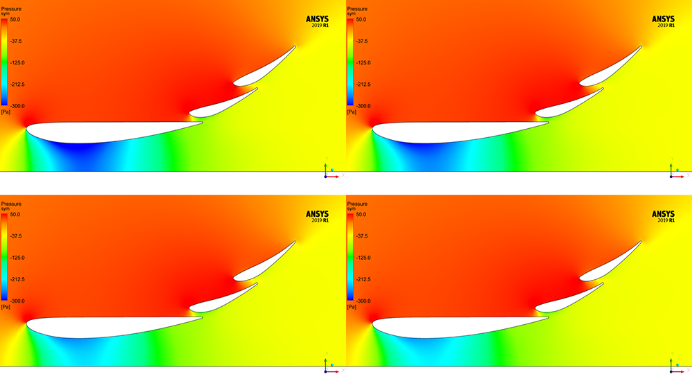
Figure 13 – Static pressure on the symmetry plane
Table 1 below shows the lift (Cl) and drag (Cd) coefficient on the wing normalised to the y+ ~ 1 result. As there was the least deviation in the static pressure, the y+ ~ 30 forces deviate the least from y+ ~ 1. The other two cases deviate by a larger amount, showing how important it can be to resolve the viscous sublayer to accurately predict forces on the wing. As previously discussed, if computational resources are not available, a larger y+ will not significantly affect these results.
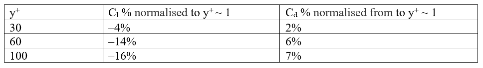
Table 1 – Lift and drag coefficients normalised to the y+ ~ 1 results
This blog series focuses on a common question: What y+ should I use in my simulations? To answer this question, the blog is broken into 3 parts in this series: stay tuned for Part 3 in this series!
- Part 1 – Understanding the physics of boundary layers
- Part 2 – Resolving each region of the boundary layer (this blog you've just finished reading!)
- Part 3 – Understanding impact of Y+ and number of prism layers on flow resolution


